


Chapter 5: Troubleshooting
To configure the motherboard jumpers and set up the BIOS
5–38
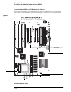
The jumpers you must check are J5, J6, J7, J8, J14 and J15. You must also install a 2.9 V VRM
module in the VRM socket. In addition, you need to ensure that the CPU fan is connected to J13
once the CPU is installed; failure to connect the fan will cause the CPU to overheat and
malfunction.
CAUTION AVOID DAMAGE TO THE CPU BY CORRECTLY CONFIGURING THE JUMPERS!
You must configure J5, J6, J7, J8, J14 and J15 before installing the CPU and applying power to
the motherboard. Failure to configure these jumpers correctly may damage the CPU.
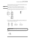
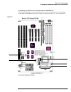
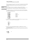
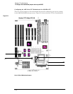
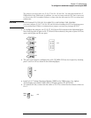
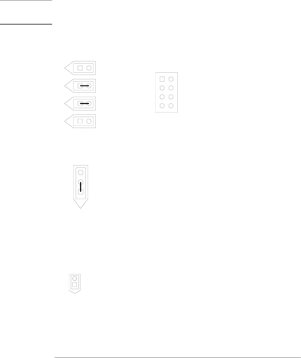
• To configure the jumpers, set J5, J6, J7, J8, and J14 as shown in the following figure.
Note that the pairs of pins on J6 and J7 are shorted; the pairs of pins on J5 and J8 are
open; and all pins on J14 are open.
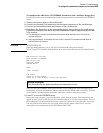
• The processor must be configured for a 66 (33) MHz PCI bus clock speed by shorting
pins 1 and 2 on J15 as shown in the following figure.
• Install a 2.9 V Voltage Regulator Module (VRM) in the VRM socket. Use Agilent
Technologies part number 0950-2794 (VXI part number 073-20723-29 or Corsair part
number SP5260TS-2X9).
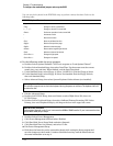
• To connect the fan, connect the fan cable to J13. The colored fan lead must connect to
Pin 1.
J6
J7
J8
J14
J5
J15
J13
Pin 1
GND
+12V