


Chapter 5: Troubleshooting
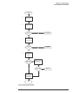
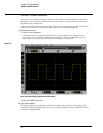
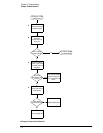
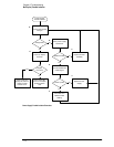
No Display Trouble Isolation
5–10
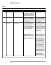
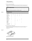
Table 5-1
Power-On Sequence with External Monitor Connected
Time Audible Indicators Visible Indicators Description Troubleshooting
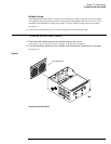
1 Power-on Power-on the instrument and listen
for the fans and the hard disk drive.
The hard disk is located behind the
floppy drive against the chassis side
wall.
2 Fans begin running Power switch LED illuminates The main instrument fan and the
CPU fan start running at power on.
The LED located behind the front
panel power switch is connected to
the +5 V supply, making it a good
power supply indicator.
You will need to use a DMM to
verify that the supply voltages
are within specifications. If the
power supplies do not come up,
go to the “Power Supply Trouble
Isolation” flowchart
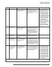
3 HDD (hard disk drive)
begins turning
Front panel LEDs come up in
power-on pattern
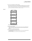
The front panel LEDs display their
power-up pattern. The following
trigger LEDs should all come on at
the same time: Edge, Glitch,
Advanced, Positive and Negative
slope, DC, AC, LF Reject, and HF
Reject. This pattern indicates that
the front panel keyboard has
completed its power-on test.
If the LEDs do not come on,
check the cabling to the front
panel board and check for +5 V
on pin 2 of the 10-pin conductor
keyboard cable W16. Also check
for +5 V on the scope interface
card A6. If the +5 V is at the scope
interface card but the front panel
LEDs do not come on, the
problem is the cable or the front
panel keyboard A7.
The hard disk drive (HDD) starts
spinning at power on. Listen at the
top right rear of the instrument for a
higher-pitched whine; this is the
HDD coming up to speed. Shortly
after the disk comes up to speed,
you should hear a brief burst of
clicks*; this sound is part of the
disk's power-up self-check routine.
If the HDD is not responding,
check the cabling. If the disk is
turning, but you do not hear the
brief burst of clicks after the disk
comes up to speed, the circuitry
onboard the disk drive may be at
fault. If the motherboard
(including CPU and RAM) are
functioning but the HDD is not
responding, the external VGA
monitor will usually show the
message "16000 KB OK, WAIT..."
followed by the message "Pri
Master HDD Error, RUN SETUP,
Press F1 to Resume. See “To
configure the motherboard
jumpers and set up the BIOS” on
page 5-29. for information on
how to access and run the setup
program. If, after running setup,
there is still a problem, check the
cabling for the hard disk drive,
both between the motherboard
and SVGA display board, and
between the SVGA display board
and the HDD. If the cabling is OK,
see the section on verifying
motherboard operation;
otherwise, replace the HDD.
* Later model hard disk drives are much quieter than earlier models.
The clicking can only be heard with the instrument sleeve removed and in close proximity to the hard disk drive.