Chapter 8: Theory of Operation
Attenuator Theory
8–7
Attenuator Theory
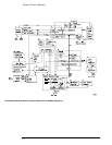
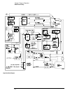
The channel input signals are conditioned by the dual channel attenuator assemblies. There are
two completely independent attenuators on each assembly, but one channel can be routed in
the preamp/multiplexer hybrid to drive both channel outputs for sample rate doubling purposes.
Each channel contains passive attenuators, an impedance converter, and a programmable gain
amplifier. There are two identical outputs for each channel: one to drive the ADC hybrids and
one to drive the trigger circuitry.
The channel input impedance is selectable between 1 M
Ω and 50 Ω. The 50 Ω path consists of
high-frequency 5:1 and 10:1 attenuators and the preamp/multiplexer hybrid, which allows gain-
switching between 1:1 and 2:1. This combination of attenuators and gain allows channel
sensitivities in the standard 1-2-5 sequence from 10 mV/div to 1 V/div. For sensitivities other
than these, full resolution ranges software expansion is performed. The preamp/multiplexer
hybrid also provides offset adjustment for the 50
Ω path.
The 1 M
Ω path consists of a 10:1 attenuator and a 1 MΩ to 50 Ω impedance converter. Once
converted to 50
Ω, the signal is routed back to the 50 Ω path (described above) for further
attenuation and amplification. Compensation for the 1 M
Ω 10:1 attenuator is adjusted at the
factory and does not require readjustment.
After the passive attenuators, the signal is split into high-frequency and low-frequency
components. Low-frequency components are amplified on the main assembly where they are
combined with the offset voltage. The ac coupling is implemented in the low-frequency amplifier.
The high- and low-frequency components of the signal are recombined and applied to the input
FET of the impedance converter. The FET provides a high impedance load for the input
attenuators and a low impedance drive for a buffer, which drives 50
Ω.
Acquisition Theory
The acquisition system includes two major sections. One is the acquisition board, which
conditions, stores, and processes the input signals. The other is the scope interface board, which
provides the interface from the acquisition to the motherboard and display, and also interfaces
the motherboard to the front-panel keyboard.
Acquisition Board
The acquisition circuitry samples, digitizes, and stores the signals from the channel attenuators.
The four channels are identical. The trigger signals synchronize acquisition through the trigger
and time base circuitry. A reference oscillator and the time base provide the base sample rates.
ADC Hybrid The Agilent Technologies 54845A ADC hybrid provides all of the sampling,
digitizing, and high-speed waveform storage. Each ADC hybrid contains two 2 GSa/s ADCs.
They can be run in phase to increase resolution, or out-of-phase to sample at 4 GSa/s. The
ADC includes a delay-locked loop to synchronize the 2 GHz sample clock to the 100 MHz
timebase reference clock. For sample rates < 2 GSa/s, data is decimated.


