


Chapter 6: Replacing Assemblies
To remove and replace the probe power and control assembly
6–8
To remove and replace the probe power and control assembly
Use this procedure to remove the probe power and control assembly. When necessary, refer to
other removal procedures.
1
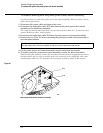
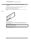
Disconnect the power cable and remove the cover.
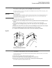
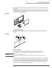
2 Disconnect the mylar flex cable W13 that connects the probe power and control
assembly to the AutoProbe assembly.
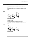
The connector must be unlocked before you can remove the flex cable. See “To disconnect and
connect Mylar flex cables” in this chapter.
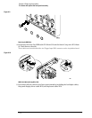
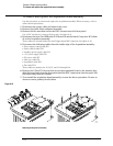
3
Disconnect the mylar flex cable W12 from the probe power and control assembly.
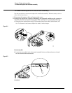
4 Remove the two Torx T10 screws securing the probe power and control assembly to
the front panel chassis.
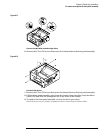
5 Lift the probe power and control assembly out and away from the chassis.
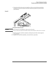
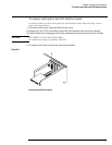
6 To replace the probe power and control assembly, reverse the above procedure.
When inserting the assembly, be sure the two tabs on the circuit board engage the two slots in
the sheet metal. Also, be sure to carefully lock in the connector for the mylar flex cable when
reattaching the cable. See “To disconnect and reconnect mylar flex cables” in this chapter.
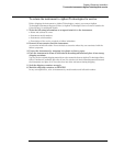
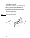
Figure 6-7
Removing the Probe Power and Control Assembly
Avoid Interference with the Fan
You may need to use a Torx key or stubby Torx driver to avoid interference with the fan.
W13
W12