


Chapter 6: Replacing Assemblies
To remove and replace the backlight inverter board
6–9
To remove and replace the backlight inverter board
Use this procedure to remove and replace the backlight inverter board. When necessary, refer
to other removal procedures.
WARNING SHOCK HAZARD!
The backlight inverter assembly, which is mounted at the front corner of the instrument near
the flat-panel display, operates at high voltages from 300-1 kV ac
rms
. DO NOT handle this
assembly while it is in operation.
1
Disconnect the power cable and remove the cover.
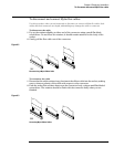
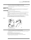
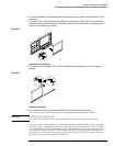
2 Disconnect the two backlight cables from the top and bottom of the backlight inverter
board.
You can either stand the chassis on end or turn it over to gain access to both cables.
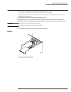
3 Disconnect the backlight primary cable W17 from the side of the backlight inverter
board.
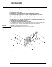
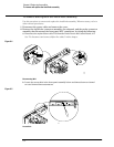
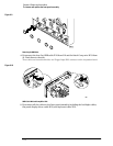
4 Remove the 2 Torx T10 screws that secure the backlight inverter board to the chassis.
5 Lift the backlight inverter board out through the top of the chassis.
6 To replace the backlight inverter board, reverse the assembly procedure.
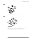
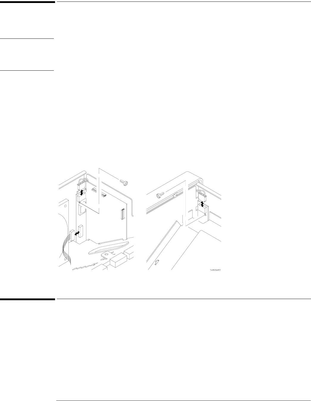
Figure 6-8
Removing the Backlight Inverter Board
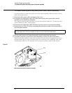
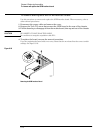
To remove and replace the front panel assembly
Use these steps to remove and replace the front panel assembly. When necessary, refer to other
removal procedures.
1
Disconnect the power cable and remove the cover.
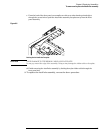
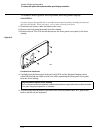
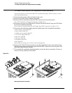
2 Remove the Quick-Probe assembly and Mylar flex cable W13.
3 Remove the hex nuts that secure the BNC connectors to the front panel.
Use a 9/16” nut-driver to remove the hex nuts.