


Chapter 6: Replacing Assemblies
To remove and replace the front panel assembly
6–11
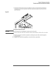
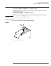
Figure 6-11
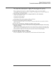
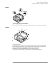
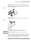
Disconnecting W16, W20, and the Backlight Cables
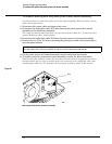
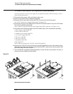
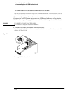
6 Remove the 4 Torx T15 screws that secure the chassis sides to the front panel assembly.
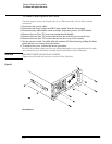
Figure 6-12
Front Panel Side Screws
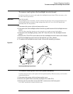
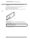
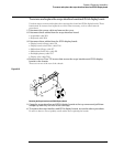
7 Remove the 2 Torx T10 screws that secure the chassis front to the front panel assembly.
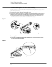
8 Pull the front panel assembly away from the chassis, being careful to feed the ribbon
cables W16 and W20 out through the slot in the front of the chassis.
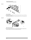
9 To replace the front panel assembly, reverse the above procedure.
Ensure that you observe polarity designations when reconnecting the ribbon cables.