


Chapter 3: Testing Performance
To test trigger sensitivity
3–25
17
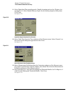
Adjust the horizontal sweep speed to 1 ns/div.
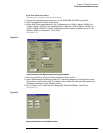
18 Adjust the trigger level for a stable display.
19 The test passes if triggering is stable. Record the result in the Performance Test Record.
20 Connect the signal generator to the channel 2 input.
21 Repeat steps 4 through 20 for the remaining channels.
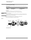
Procedure—Auxiliary Trigger Test
The auxiliary trigger input is on the front panel of the oscilloscope near the vertical inputs. The
dc input resistance of the aux trigger is 2.58k
Ω, so to avoid reflections, the trigger source is back-
terminated with 50
Ω.
1 With an N-to-BNC adapter and BNC cable, connect the signal generator to the input of
the power splitter. Connect one output of the power splitter to the Aux Trig input
through a 50
Ω feedthrough termination. Connect the other output of the power splitter
to channel 1.
2 Set the signal generator for 500 MHz, approximately 0 dBm.
3 Set the channel 1 input to 50-Ω input impedance and press Autoscale.
4 Set the channel 1 scaling to 50 mV/div. Then set the signal generator for 6 divisions of
signal (300 mV
pp
).
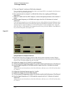
5 Press the Source key (Trigger section of front panel) to highlight Aux.
6 Set the trigger level to 0.000 V.
7 Slowly adjust the Trigger Level knob slightly around the 0 V setting to obtain a stable
trigger. Otherwise, the test fails. Record the result in the Performance Test Record.
If a test fails
Failure of the internal trigger or external trigger sensitivity tests can be caused by a defective main
assembly or attenuator. Failure of the auxiliary trigger sensitivity is caused by a problem on the main
assembly or a bad input cable. If you need further troubleshooting information, go to chapter 5,
“Troubleshooting.”