


Chapter 5: Troubleshooting
To check the backlight inverter voltages
5–23
To check the backlight inverter voltages
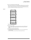
The backlight inverter board A3 is located in the front-left corner of the oscilloscope (as you face
the front panel).
• There is one input connector on the side of the board.
• There are two output connectors, one at each end of the board (top and bottom), which power
the two backlights inserted into the flat panel display.
The output voltage is approximately 300-450 V
rms
, 40 kHz (measured differentially between the
two wires) when the backlight is illuminated. The voltage is approximately 1 kV before the
backlight tube is illuminated.
The outputs are controlled by the input. Notice that input pin 5 goes low to enable the output
voltage. These pins can be reached at J1 on the SVGA display board A5.
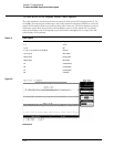
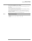
Table 5-6
Backlight Inverter Board Input Voltages
Input Pin # 7 65432 1
Backlight OFF 0 V 0 V 12 V 0 V 0 V 12 V 12 V
Backlight ON 0 V 0 V 0 V 0 V 0 V 12 V 12 V