


Chapter 6: Replacing Assemblies
To remove and replace the acquisition board assembly
6–14
To remove and replace the acquisition board assembly
Use this procedure to remove and replace the acquisition assembly. When necessary, refer to
other removal procedures.
1
Disconnect the power cable and remove the cover.
2 Remove the Quick-Probe subpanel assembly.
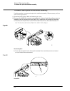
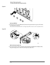
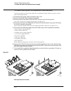
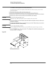
3 Remove the hex nuts that secure the BNC connectors to the front panel.
Use a 9/16” nut-driver to remove the hex nuts. See figure 6–9.
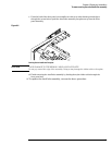
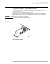
4 Disconnect the Aux Out SMB cable W18 from J10 and the black Comp wire W19 from
J4 on the Acquisition assembly.
These cables are located behind the Aux Trigger Input BNC connector. See figure 6–10.
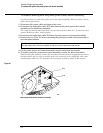
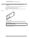
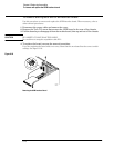
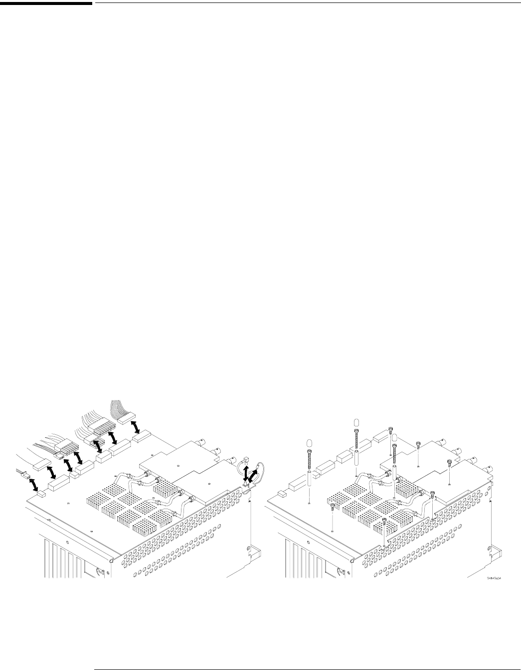
5 Disconnect the following cables from the inside edge of the Acquisition assembly:
• Power supply control cable W2
• Probe control cable W12
• Auxiliary power supply cable W4
• +5 V power supply cable W3
•PC power cable W5
• Line sync cable W6
• Acquisition cable W11
• Fan cable W21
These cables are attached to J2, J3, J5, and J11 through J16.
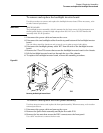
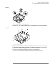
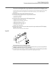
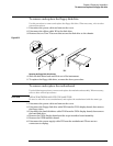
6
Remove the 9 Torx T10 screws that secure the acquisition board to the chassis, then
slide the board back from the front panel until the BNC connectors clear the panel. Lift
the board away from the chassis.
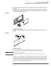
7 To re-install the acquisition board assembly, reverse the above procedure. Be sure to
observe correct polarity for all cables.
Figure 6-16
Removing the Acquisition Assembly