


Chapter 5: Troubleshooting
Power Supply Trouble Isolation
5–15
E
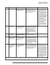
Check +15 V Bias and Remote Inhibit cabling.
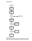
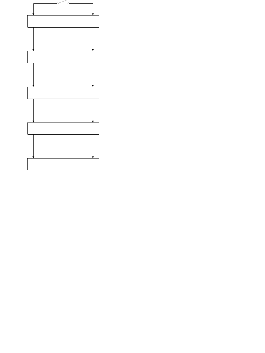
If the oscilloscope will not power up, check all cabling to troubleshoot and correct the problem.
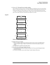
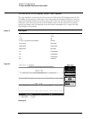
Figure 5-4 shows the routing of the +15 V Bias and Remote Inhibit signals from the front panel
to the power supply. The power supply is on only when the remote inhibit signal is between
+1 V and +5 V. A problem could be caused by a faulty cable or bad connector anywhere in this
path. Check all the cables and connections and replace any at fault.
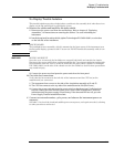
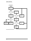
Figure 5-5
Routing of +15 V Bias and Remote Inhibit Signals
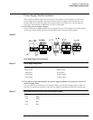
F Replace the power supply.
1 If the +15 V bias is correct, but the instrument will not power up with a 196-220Ω resistor,
replace the power supply. Chapter 6 explains how to remove and replace the power
supply.
2 Re-assemble the instrument and apply power.
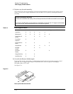
G
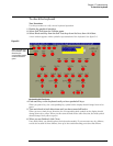
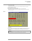
Check for the oscilloscope display onscreen.
1 You should see the oscilloscope display (see figure 5-2). If not, see the No Display Trouble
Isolation Flowchart.
2 If you see the display, return to the Primary Trouble Isolation Flowchart.
A8 Cursor Keyboard
A1 Power Supply
A13 Acquisition Board
A6 Scope Interface Board
A7 Front Panel Keyboard
Front Panel Power
Switch
9
11
J11
J16
4955
4955
J2
J3 31
31
W15
W16
W11
W2
Remote Inhibit+15 V Bias