


Chapter 5: Troubleshooting
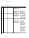
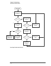
Power Supply Trouble Isolation
5–14
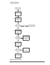
C
Replace any shorted assembly.
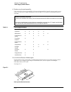
You can locate the shorted assembly by disconnecting assemblies from the power supply, one at
a time. Use the power supply distribution chart in table 5-4 as a guide to locating the shorted
assembly.
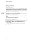
Table 5-4
Power Supply Distribution
D
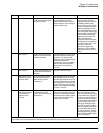
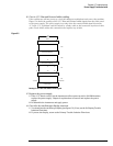
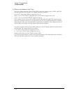
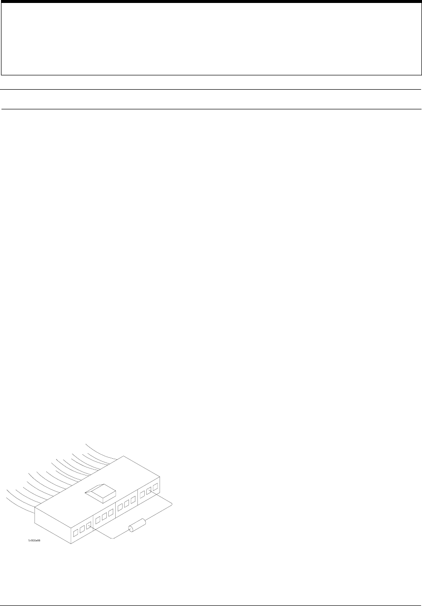
Override the Remote Inhibit signal.
Power up the unit by connecting a resistor between pin 3 and pin 11 of power supply control
cable W2. Use a resistor in the range of 196-220
Ω, 1/8 W, such as Agilent Technologies
P/N 0698-3440 or 0757-0407.
See figure 5-4.
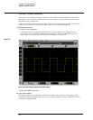
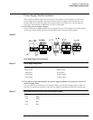
Figure 5-4
Power-up Sense Resistor Connection
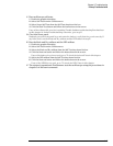
Reconnect Assemblies and Cables
Reconnect all assemblies after testing. The oscilloscope must have all cables connected for correct power
up.
If you want to test the power supply without any assemblies connected, the +5 V supply must be loaded
to 2 A. Use two 5
Ω, 10W resistors between the +5 V output and ground.
Assembly +5.1 V -5.2 V Ground +12.2 V -12.2 V 3.3 V (generated on Motherboard)
Acquisition X X X X X
Motherboard X X X X X X
Probe Power &
Control
XXXX
Front-Panel
Keyboard
XX
Scope Interface
Board
XX X
Display Board X X X X X
Backlight
Inverter
XX
Flat Panel
Display
XX X
Floppy Disk Drive X X
Hard Disk Drive X X