


Chapter 5: Troubleshooting
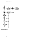
To troubleshoot attenuator failures
5–56
To troubleshoot attenuator failures
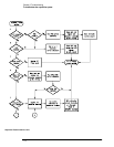
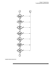
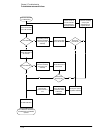
The best method for troubleshooting attenuator assembly failures is to swap the suspected one
with a known good one. This discussion will help you determine whether the attenuator or
acquisition board is causing a problem.
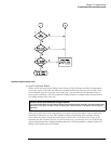
The attenuator assembly consists of attenuators and a preamplifier for two channels. The
attenuator assembly contains the following:
• A relay for selecting input resistance (50
Ω or 1 MΩ)
• Two switchable attenuators (1:1/5:1 and 1:1/10:1) which can be cascaded to provide
attenuation ranges of 1:1, 5:1, 10:1, and 50:1 in the 50
Ω path
• An impedance conversion circuit in the 1 M
Ω path
• A programmable preamplifier and multiplexer for 1x and 2x gain
Defective attenuators can cause a variety of symptoms.
• Wrong input resistance
• Low bandwidth/slow rise time
• Signal distortion
• Calibration failures
•Self-test failures
Firmware Calibration should also be done after attenuator replacement (see chapter 4,
“Calibrating and Adjusting”).
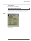
Attenuator Click Test
The solenoids for the passive attenuators can be heard switching when the vertical sensitivity is
changed. However, the gain calibration will give different switching points to different attenuator
assemblies. Individual attenuator assemblies will not necessarily switch at the same sensitivities.
Check for switching sounds between the following range changes:
• 20 to 50 mV/div
• 100 to 200 mV/div
• 200 to 500 mV/div
• 1.0 to 2.0 V/div
You can hear relays switching when going either direction through the transitions.
You can hear the input path relay when the input resistance is changed. Toggle the input
resistance button for each channel.
If either of the click tests fail, the attenuator assembly may be defective.