


3-11
April 2004
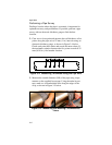
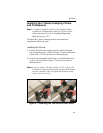
Installing the Transducers
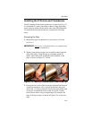
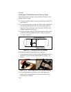
1. Apply a bead of couplant 6 mm (0.25 in.) wide along the
entire length of each transducer face, as shown in Figure 3-10
below.
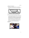
Figure 3-10: Couplant on Transducer Face
Note: Do not slide the transducer with couplant along the
surface of the pipe when mounting the transducer.
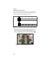
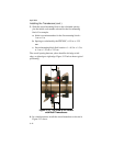
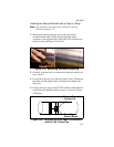
2. Set the first mounting block (either left edge or right edge) at a
convenient number on the scale, such as 1 in. or 1 cm. Install
the first transducer with the BNC connector pointing away
from the center of the V block fixture. Tighten the transducer
mounting thumbscrew onto the slider, which in turn applies
pressure to the transducer. Use a handtight grip to set the
transducer in contact with the pipe, as shown in Figure 3-11
below. Use a wrench to tighten the backing nut to prevent
loosening due to vibration and thermal expansion.
IMPORTANT: Do not use a wrench or pliers on the
thumbscrew.
Figure 3-11: Installing the First Transducer