


Ultrasonic Thickness Gauge Theory of Operation C-1
April 2004
Appendix C
Ultrasonic Thickness Gauge
Theory of Operation
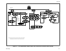
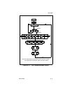
All ultrasonic thickness gauging involves timing the round trip of
a sound pulse in a test material. Because solid metal has an
acoustic impedance that differs from that of gases, liquids, or
corrosion products such as scale or rust, the sound pulse will
reflect from the far surface of the remaining metal. The test
instrument is programmed with the velocity of sound in the test
material, and computes the wall thickness from the simple
formula
Distance = Velocity × Time
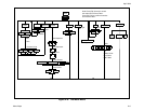
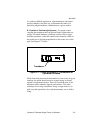
Single element transducers use one element as both transmitter
and receiver. Dual element transducers incorporate separate
transmitting and receiving elements. These elements are mounted
on delay lines that are usually cut at an angle to the horizontal
plane (the roof angle), so that the transmitting and receiving beam
paths cross beneath the surface of the test piece. This crossed-
beam design of duals provides a pseudo-focussing effect that
optimizes measurement of minimum wall thickness in corrosion
applications. Duals are more sensitive than single element
transducers to echoes from the base of pits that represent
minimum remaining wall thickness. Also, duals may often be
used more effectively on rough outside surfaces. Couplant
trapped in pockets on rough sound entry surfaces can produce
long, ringing interface echoes that interfere with the near surface
resolution of single element transducers. With a dual, the receiver
element is unlikely to pick up this false echo. Finally, duals may
be designed for high temperature measurements that would
damage single element contact transducers.