


April 2004
3-8
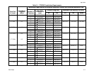
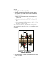
Obtaining the Transducer Spacing
1. Using the measured OD and the pipe wall thickness, program
the PT878GC (discussed in Chapter 4, Programming Site
Data) to determine the required transducer spacing.
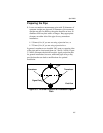
2. To determine the PT878GC correction factor, calculate the
mean inside pipe diameter (ID) and the pipe ID at the
transducer locations. Then divide the square of the mean ID
by the square of the ID at the transducer location, as shown in
the equations below, where OD
X
is the outside diameter at a
given point, and W
X
is the wall thickness at a given point (as
shown in Figure 3-6 on the previous page).
(3-1)
(3-2)
3. Program the value into the PT878GC.
Note: See Chapter 4, Programming Site Data, pages 4-3 to 4-16,
for more details on programming.
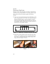
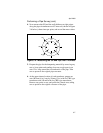
Based on the pipe OD, proceed to the appropriate section:
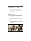
• If the pipe is < 12” (300 mm), see the section Installing the V
Series Clamping Fixture and Transducers on the next page.
• If the pipe is > 12” (300 mm), go to Installing the PI Fixture
and Transducers on page 3-12.
mean ID OD
1
W
1
W
5
+()–()OD
2
W
2
W
6
+()–()
OD
3
W
3
W
7
+()–()OD
4
W
4
W
8
+()–()
+
++
(
) 4⁄
=
K
for non-concentric pipe
Mean ID
2
()
ID at transducer location()
2
-------------------------------------------------------------------=