


vii
Contents
1 Introduction 1..............................................
1.1 MintDrive f eatures 1.........................................................
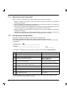
1.2 Receiving and inspection 2...................................................
1.2.1 Identifying the catalog number 2.................................................
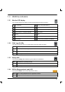
1.3 MintDrive indicators 3.......................................................
1.3.1 Monitor LED display 3..........................................................
1.3.2 CAN 1 and 2 LEDs 3...........................................................
1.3.3 Ready LED 3.................................................................
1.3.4 DB On (Regeneration Load) LED 3...............................................
1.4 Units and abbreviations 4....................................................
2 Basic Installation 5.........................................
2.1 Outline 5..................................................................
2.1.1 Hardware requirements 5.......................................................
2.1.2 RS485 / RS422 systems 7......................................................
2.1.3 Power sources 7..............................................................
2.1.4 Tools and miscellaneous hardware 7.............................................
2.1.5 Other information needed for installation 7.........................................
2.2 Mechanical i nstallation and location requirements 8..............................
2.2.1 Dimensions and mounting 9.....................................................
2.3 Power c onnections 10........................................................
2.3.1 Grounding 11..................................................................
2.3.2 Input power conditioning 12......................................................
2.3.3 Power disconnect and protection devices 12........................................
2.3.4 Wire sizes 14..................................................................
2.3.5 Single phase connection to package size A or B 15..................................
2.3.6 Single phase connection to package size C 15......................................
2.3.7 Three phase connection to package size C 16......................................
2.3.8 24V control supply 16...........................................................
2.3.9 DC Bus power connections from package size C 17.................................
2.3.10 Power supply filters 18..........................................................
2.4 Motor connections 19.........................................................
2.4.1 Motor circuit contactors 20.......................................................
2.4.2 Regeneration resistor (Dynamic Brake resistor) 21...................................
2.5 Feedback connections 22.....................................................
2.5.1 Resolver option 23..............................................................
2.5.2 Encoder option 25..............................................................
2.6 Drive enable 26..............................................................