


120
B.3.2 Preparing the MintDrive
Termination resistors must be fitted at each end of the network to reduce signal reflection.
The MintDrive is fitted with a termination resistor for this purpose.
On the front panel of your MintDrive the termination resistor should be selected by setting the CAN2
DIP into the ON position.
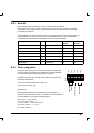
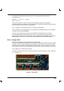
B.3.3 Preparing the C AN peripheral
Termination resistors must be fitted at the ends of the network to reduce
signal reflection.
The CAN peripheral is fitted with a termination resistor for this purpose.
If the CAN peripheral is at the end of the CAN network, the termination
resistor can be selected by fitting a jumper to JP3.
Also, when connecting a CAN peripheral to a MintDrive controller, the
peripheral’s CAN Bus channel 2 must be selected by fitting jumpers J P1
and JP2 to position 2.
Jumpers JP4 and JP5 should not be fitted at this stage.
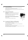
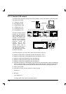
B.3.4 Connecting the PC, MintDrive and CAN peripheral
Connect the CAN peripheral to the MintDrive using a s uitable CAN cable.
Connect the CAN peripheral to a 24VDC supply.
If it is not already connected, connect the MintDrive to the PC using a suitable RS232 cable.
Power up the PC and the MintDrive.
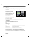
Start Mint WorkBench and open the Terminal window (CTRL+T).
Press the Enter key to display the C> prompt. If the prompt does not appear, press CTRL+E. This will
end any program that might be running on the MintDrive.
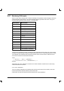
}
1
2
CAN Bus
Channel
CAN Terminator
Configuration
JP3
JP5
JP4
JP2
JP1