


39
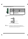
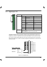
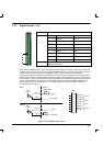
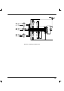
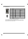
3.3.3 Digital Outputs - X13
Location Connector X13
Pin Name Mint keyword
13 DOUT5- OUT.5
14 DOUT5+ OUT.5
15 DOUT6- OUT.6
16 DOUT6+ OUT.6
17 DOUT7- OUT.7
18 DOUT7+ OUT.7
19 DOUT8- OUT.8
20 DOUT8+ OUT.8
Description Four general purpose optically isolated digital outputs
(DOUT5 to DOUT8).
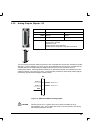
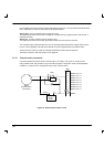
Each optically isolated output may be configured for either sinking or sourcing current up to a maximum
of 50mA on each output. The maximum saturated voltage across any of these outputs when active is
1.0VDC, so they can be used as TTL compatible outputs. These outputs can have a mixed
configuration, with some sinking current while others source current. However, if the outputs are used
to directly drive a relay, a suitably rated flyback diode must be fitted across the relay coil, observing the
correct polarity. This is to ensure that an output is protected from the back -EMF generated from the coil
when it is de -energized. The outputs are updated every 30.72ms and can be written to directly using
the Mint keyword OUT (for example OUT.5). If a faster response is required, DOUT0~DOUT4 on
connector X5 can be used.
DOUT5 -
X13
13
DOUT5+
14
DOUT6 -
15
DOUT6+
16
DOUT7 -
17
DOUT7+
18
DOUT8 -
19
DOUT8+
20
Typical
DOUT-
USR GND
50mA
maximum
Relay &
Flyback diode
USR V+
DOUT+
Typical
DOUT-
USR GND
50mA
maximum
USR V+
DOUT+
Sink
Source
OUT.5
OUT.6
OUT.7
OUT.8
Figure 18 - X13 Digital output circuit
13
20