


30
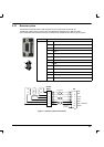
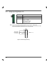
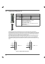
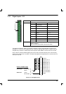
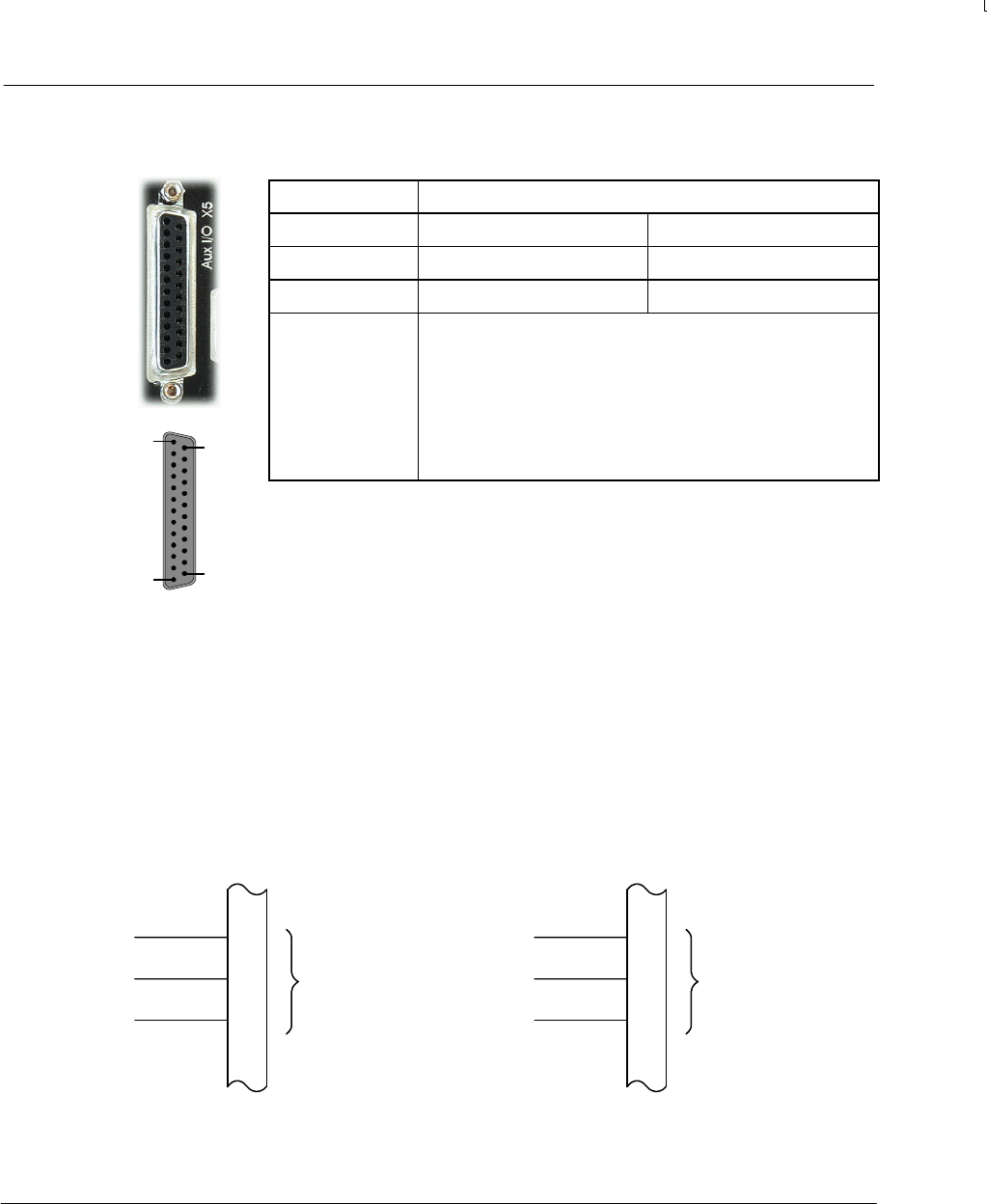
3.2.3 Analog Inputs, Differential - X5
Location Connector X5
Pins 8 (+) and 21 ( -) 9 (+) and 22 (-)
Name AIN0 AIN1
Mint keyword ADC.0 ADC.1
Description Two independent differential inputs.
Common mode voltage range: ±10VDC.
Resolution: 12-bit with sign.
Common mode rejection: 40dB
Input impedance: >22kΩ
Sampling interval: 0.5ms - 20ms (depends upon servo
loop frequency).
Accuracy: better than 1%
Typical use for these may be analog sensor inputs or to provide a low cost joy-stick interface.
The guaranteed DC accuracy of the inputs is 2%. Each input is buffered individually, before being fed
into separate channels of the ADC, a Maxim MAX197. There is some input protection should the input
voltage exceed the maximum rating shown above, although this is for protection against transitional
over-voltage; long term over-voltages will cause permanent damage.
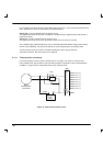
Each analog input signal should be connected to the system using a screened/shielded twisted pair
cable, and the cable shield should be connected to the chassis at one end. Due to the differential
characteristics of these inputs, they can provide better rejection of common mode noise provided
normal good engineering practices are adhered to. No other connection should be made to the cable
shield.
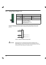
AIN0 (ADC.0)
8
21
X5
Input +
Input -
20
GND
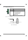
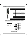
AIN1 (ADC.1)
9
22
X5
Input +
Input -
20
GND
Figure 12 - AIN0 and AIN1 analog inputs
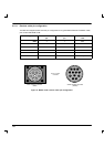
1
13
25
14