


40
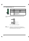
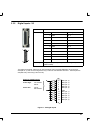
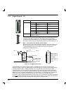
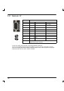
3.3.4 Digital Outputs - X5
Location Connector X5
Pin Name Mint keyword
10 DOUT4 OUT.4
11 DOUT2 OUT.2
12 DOUT0 OUT.0
23 DOUT3 OUT.3
24 DOUT1 OUT.1
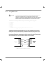
Description Five general purpose optically isolated digital outputs
(DOUT0 to DOUT4).
These general purpose optically isolated outputs can only be used to source
current from the USR V+ rail (pin 25). The output current source passes
through the load to USR GND (pin 13). The outputs are updated immediately
andcanbewrittentodirectlyusingtheMintkeywordOUT (for example OUT.4).
Note: The outputs have different current ratings!
DOUT0 is a high current output, rated at a maximum continuous current of 1A.
DOUT1~DOUT3 are lower current outputs, rated at a maximum continuous
current of 250mA on each output. There is no minimum current load
requirement for DOUT0~DOUT4.
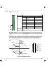
DOUT4 (OUT.4)
X5
10
DOUT2 (OUT.2)
11
DOUT0 (OUT.0)
12
USR GND
13
DOUT3 (OUT.3)
23
DOUT1 (OUT.1)
24
USR V+
25
X5--13
X5--25
USR V+
S
D
Relay coil with
flyback diode
USR GND
VN330SP
output
driver
(250mA max)
OUT.4
X5--10
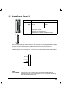
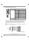
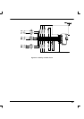
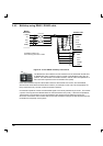
Figure 19 - X5 Digital output circuit
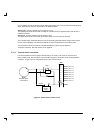
These MOSFET type outputs are driven from ST VN330SP devices and have a maximum ON
resistance of 0.4Ω. There are protection features built into each of the outputs. Under voltage sensing
means that when a USR V+ voltage of less than 10V is applied, the output will become inactive.
Thermal protection, for short circuit and over dissipation, also causes the output to become inactive.
If the combined current of all the X5 outputs exceeds 5A, there is the possibility of blowing an internal
SMD fuse, which is not easily replaceable and is non -serviceable. If a hardware fault is suspected on
these outputs, the condition can be checked (by the user’s program) using the Mint keyword
MISCERROR. If the outputs are used to directly drive a relay or an inductive load, a suitably rated flyback
diode must
be fitted across the relay coil, observing the correct polarity. This is to ensure that an output
is protected from the back -EMF generated from the coil when it is de -energized.
1
13
25
14