


27
3.1 O utline
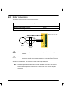
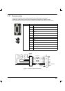
This section describes the various digital and analog input and output capabilities of the MintDrive,
together with descriptions of each of the associated connectors on the front panel.
The following conventions will be used to refer to the inputs and outputs:
I/O Input / Output...........
DIN Digital Input..........
DOUT Digital Output........
AIN Analog Input..........
AOUT Analog Output........
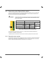
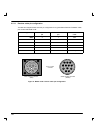
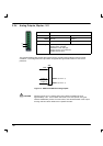
3.2 Analog I/O
The MintDrive provides:
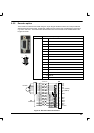
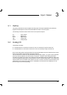
H 4 analog inputs, 2 on the block connector X11 and 2 on the 25-pin D -type connector X5
H 4 analog outputs, 2 on the block connector X11 and 2 on the 25-pin D -type connector X5.
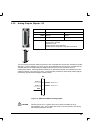
None of the analog I/O are optically isolated from internal generated power rails, therefore care must be
taken to avoid earth loops and similar associated problems.
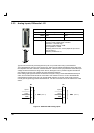
The input buffers do not offer any low pass filtering of the applied voltage. Any system noise presented
at the input will be reflected in the value read on conversion. Therefore, each analog input signal
should be connected to the system using individual screened/shielded cable (a twisted pair cable in the
case of the differential inputs) with an overall shield in order to minimize these effects. The overall cable
shield should then be connected to the chassis at one end. No other connection should be made to the
cable shield. If any inputs are unused, then it is advisable to connect them to the AGND pin. Do not
leave the inputs unconnected (floating).
3 Input / Output
3