


109
B.2 CAN 1 (CANopen)
This section provides an introduction to CANopen. peripherals and how they are configured to operate
with the MintDrive.
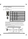
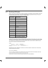
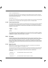
B.2.1 CAN 1 (CANopen) - X9
Location Connector X9
Pin Name Description
1 - Not connected
2 CAN1- CAN channel 1 negative
3 CAN1 0V Ground/earth reference for CAN signals
4 - Not connected
5 Shield Cable shield
6 - Not connected
7 CAN1+ CAN channel 1 positive
8 - Not connected
9 CAN1 V+ CAN remote node power V+ (12 -24V)
Description CANopen interface using a 9-pin female D -type connector
with CiA standard DS102 pin configuration
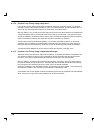
CAN1 is opto -isolated and is intended for use as the machine-wide fieldbus using the open protocol
CANopen. Practical operation of this CAN channel is limited to 500Kbaud owing to the propagation
delay of the opto-isolators.
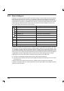
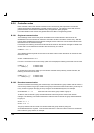
Correct operation of CAN1 can only be achieved with screened/shielded twisted pair cabling.
CAN1+ and CAN1 - must form a twisted pair with the shield connected to the connector backshell.
CAN1 must be terminated by a 120Ω resistor connected between CAN1+ and CAN1- at both ends of
the network and nowhere else.
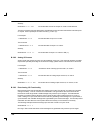
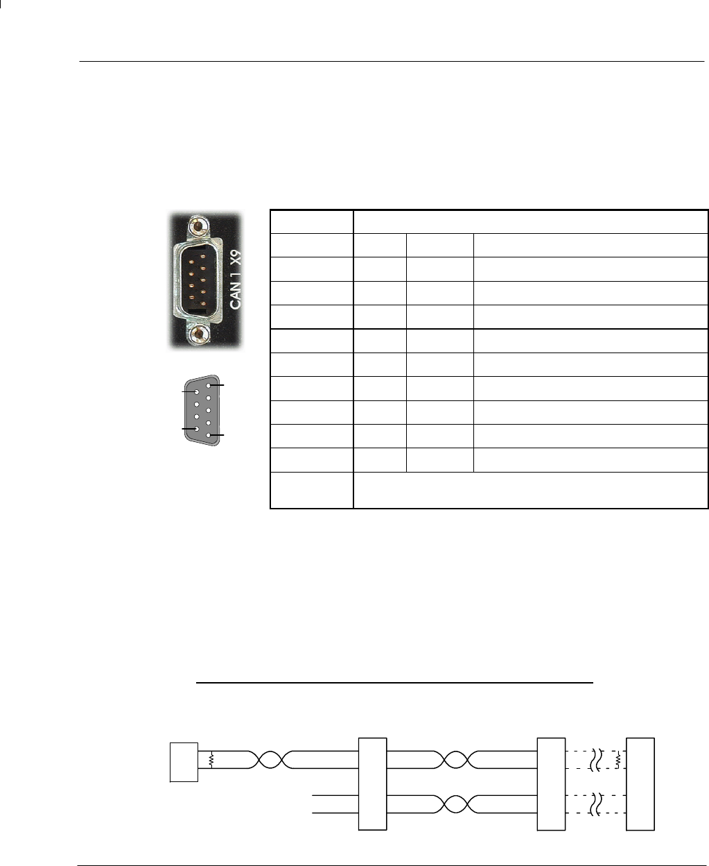
If the MintDrive is at the end of the network then ensure that the CAN1 DIP switch (located on the front
panel) is in the ON position, which will connect an internal terminating resistor. A convenient way of
wiring a chain of devices is by using a T -connector.
Note: The CAN1 port must be powered with a DC voltage in the range 12 -24V
.
2
7
9
3
2
7
9
3
CAN1
MintDrive A
CAN1
MintDrive B
2
7
Baldor HMI
Operator Panel
Twisted pair Twisted pairs
+24VDC IN
0V
T
R
T
R
End node
2
7
9
3
Figure 28 - Typical MintDrive CAN1 network connections
1
5
6
9