


38
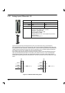
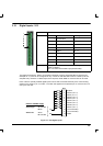
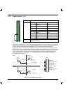
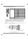
These inputs are isolated and share a single common line (COM). The entire input bank may be
configured for use in PNP mode (sinking current, where current flows in to the inputs) by connecting
COM to the negative rail of the externally generated power source. Alternatively the entire input bank
may be configured for use in NPN mode (current flows out of the inputs) sourcing current by connecting
COM to the positive rail of the externally generated power source.
The use of screened/shielded cable with the screen terminated on the D -shell is highly recommended
and will improve the inputs’ immunity to interference.
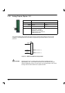
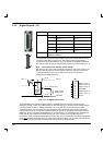
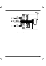
COM (pin 6) controls the sense of all the X5 digital inputs and should be permanently wired, dependent
on the user requirements, as described below:
Active high: Connect pin 6 to 0V.
The digital inputs will be active when a v oltage of +24VDC (+10VDC to +30VDC) is applied to them and
will sink a maximum of 20mA.
Active low: Connect pin 6 to +24VDC.
The digital inputs will be active when grounded (less than 2VDC) and will source a maximum of 20mA.
(To eliminate any possible errors, designs should ideally provide a “grounded” voltage of less than 1V).
The +24VDC supply mentioned above is from an externally generated 24VDC supply with an adequate
current capability to fulfill all the current requirements of the above loads. The sense of the inputs can
also be controlled individually in Mint using the keyword INPUTACTIVELEVEL.
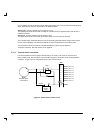
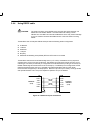
The inputs are compatible with mechanical switches or open -collector drivers. They are not, however,
compatible with external push-pull drivers unless an external diode is fitted, which effectively converts a
push-pull driver into an open collector driver.
There is a hardware propagation delay of 10µs or less between applying an external voltage and the
switch becoming active (ON). Similarly, there is a delay of 50µs or less for the device to switch OFF
when removing an external voltage.
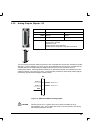
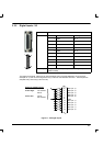
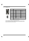
3.3.2.1 Special functions on inputs DIN0 and DIN2
DIN0 and DIN2 can be configured using the FASTAUXSELECT keyword to perform special functions:
Input
Function
DIN0 Configurable as the fast interrupt (FASTIN) hardware position capture input. The
position of the axis is captured in real time and can be read using the Mint keyword
FASTPOS. DIN0 can also be configured to capture the auxiliary encoder input as well
as the axis position input. Fitted with a Schmitt trigger device.
DIN2 Similar to DIN0, but captures the master or auxiliary encoder input which can be
read using the Mint FASTAUXENCODER keyword.
Fitted with a Schmitt Trigger device.
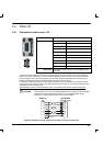
3.3.2.2 Breakout board
Connector X5 can also be connected to an I/O supporting break -out board (giving screw-terminal type
connections and local filtering). The Baldor catalog number for this item is OPT017 -501. See page 48.