


41
3.4 O ther I/O
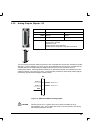
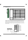
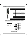
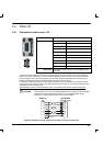
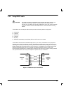
3.4.1 Simulated encoder outp u t - X3
Location Connector X3
Pin Name
1 CHA+
2 CHB+
3 CHZ+
4 (not connected)
5 DGND
6 CHA-
7 CHB-
8 CHZ-
9 (not connected)
Description Simulated encoder output on a 9-pin female D -type
connector
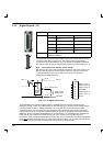
This output can be used for master slave situations where the axis movement can be transmitted to
another controller or MintDrive. It is recommended that this output only drives one output circuit load.
Driving multiple loads is not recommended. The encoder outputs are differential and conform to the
RS422 electrical specification. Shielded twisted pair cable is recommended.
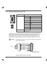
If a resolver is fitted to the MintDrive, the output resolution is 1024 ppr (pulses per revolution). This is
equivalent to a 1024 line encoder, giving 4096 quadrature counts per rev. The simulated encoder also
supports an index or marker pulse.
If the MintDrive has the encoder feedback option, X3 duplicates the encoder signals entering X2
.
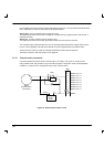
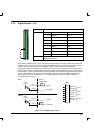
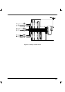
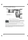
CAUTION: Using connectors X3 and X6, multiple MintDrives can be ‘daisy-chained‘ together.
However, if another Mint based controller such as a NextMoveBX is to be
connected, a special cable must be built, as shown below:
5
9
2
6
7
8
3
1
6
3
8
5
2
7
MintDrive
X3
NextMoveBX
encoder input
Connector backshell
Figure 20 - MintDrive encoder output to other Mint controller encoder input
1
5
6
9