


24
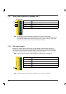
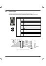
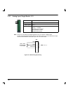
2.5.1.1 Resolver cable pin configuration
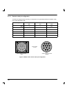
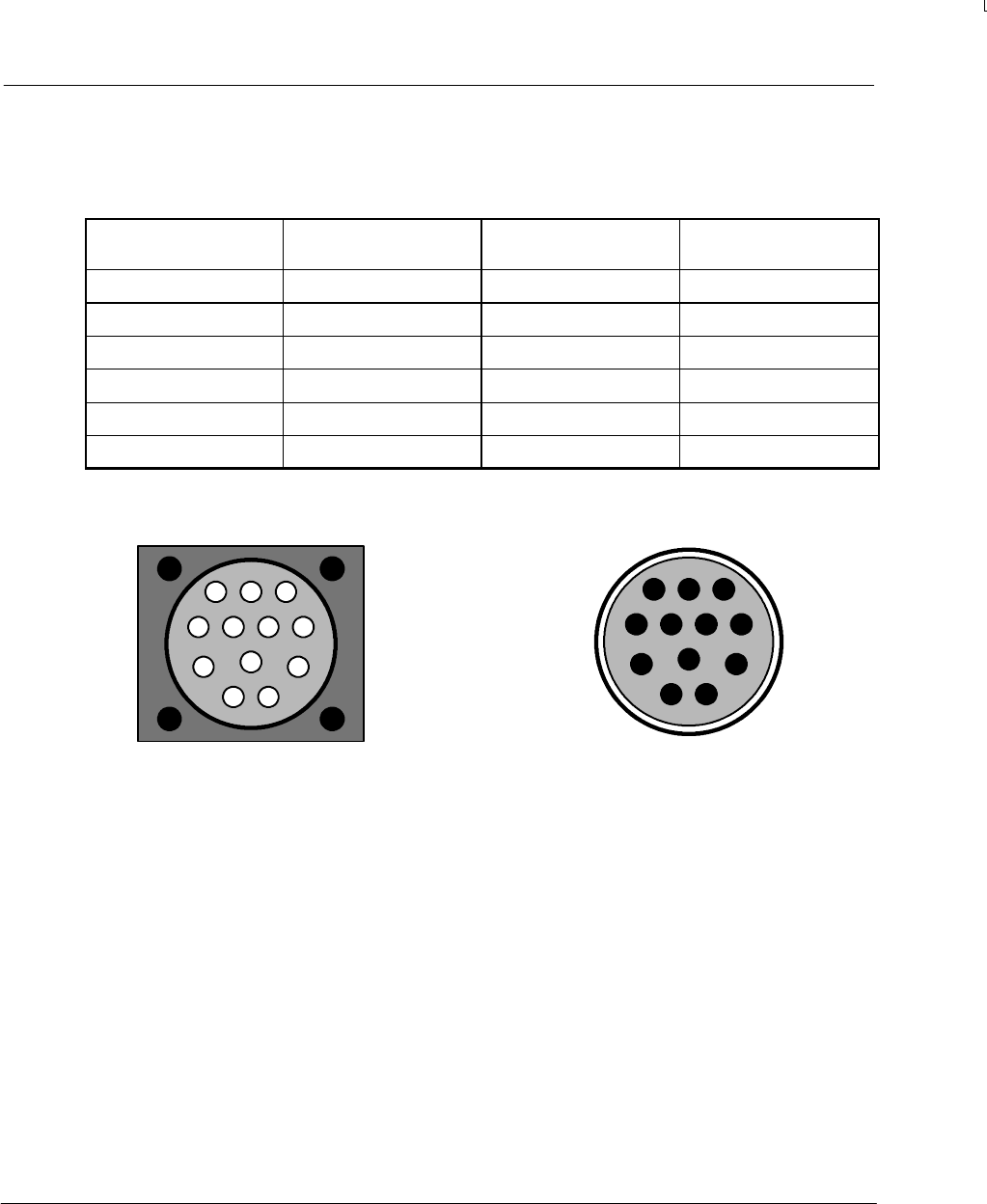
The table and diagram below show the pin configuration for a typical Baldor Resolver Feedback cable,
part number CBL030SF-ALM.
Signal name
X2
pin
Motor / cable
pin
Resolver cable wire
color
REF+ 3 1 Red
REF- 8 2 Blue
COS+ 2 3 Green
COS- 7 4 Yellow
SIN+ 1 5 Pink
SIN- 6 6 Grey
1
2
3
45
6
7
89
10
11
12
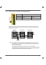
Cable connector end view
(female)
1
2
3
45
6
7
89
10
11
12
Motor resolver connector
(male)
Pins 7~12 are
not used
Figure 8 - Baldor motor resolver cable pin configuration