


97
A.1 Introduction
Within the MintDrive control software, instantaneous axis position demands produced by the MintDrive
software must be translated into motor currents. This is achieved by closed loop control of the motor.
The motor is controlled to minimize the error between the demanded and measured positions (often
known as the following error). An incremental encoder or a resolver is used to measure the motor
position. Every 1ms* the MintDrive compares demanded and measured positions and calculates the
correct demand for the motor. The corrective signal is calculated by a PIDVF (Proportional, Integral,
Derivative and Velocity Feed Forward) algorithm.
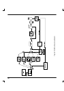
On the following page, Figure A.1 shows the MintDrive’s positional, speed and current control loops.
These are internal MintDrive control loops which can be tuned using the following keywords:
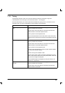
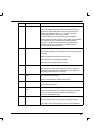
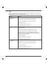
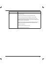
Purpose
Name Abbreviation / keyword
Position Control Proportional gain KPROP
Integral gain KINT
Velocity Feedback KVEL
Velocity Feedfoward KVELFF
Derivative gain KDERIV
Acceleration Feedforward KACCEL
Velocity Control Proportional gain KVPROP
Integral gain KVINT
Current Control Proportional gain KIPROP
Integral gain KIINT
* The 1ms sampling interval can be changed using the LOOPTIME keyword.
A Tuning
A