


10
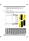
2.3 Power connections
This section provides instructions for connecting the mains supply. It is important that you refer to the
correct front panel for your MintDrive package.
The installer of this equipment is responsible for complying with NEC (National Electric Code)
guidelines or CE (Conformite Europeene) directives and application codes that govern wiring
protection, grounding, disconnects and other current protection.
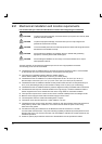
WARNING: Electrical shock can cause serious or fatal injury. Do not touch any power
device or electrical connection before you first ensure that power has been
disconnected and there is no high voltage present from this equipment or
other equipment to which it is connected.
The power supply module within the MintDrive provides rectification, smoothing, regeneration capability
(built-in on 2.5A and 5A models only) and current surge protection.
The power stage is internally fused and therefore self protected, but fuses or circuit breakers may be
used in the input lines for cable protection.
A power disconnect should be installed between the mains supply and the input of the MintDrive for a
fail safe method to disconnect power. The MintDrive will remain in a powered condition until all input
power is removed from the MintDrive and the internal bus voltage is depleted.
On units without the self generated internal 24VDC logic supply (catalog number ends with 3), you
might wish the external 24VDC logic supply to remain connected to retain position and I/O information.
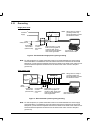
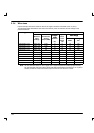
The MintDrive with package size C can accept either single phase direct (115V or 230V depending on
model) or 3 phase with transformer (250VAC max).
Note: A Residual Current Device (RCD) must not be used for fusing the drive.
All interconnection wires should be in metal conduits between the MintDrive, AC power source, motor,
host controller and any operator interface stations. Use UL listed closed loop connectors that are of
appropriate size for the wire gauge being used. Connectors are to be installed using only the crimp tool
specified by the manufacturer of the connector. Only class 1 wiring should be used.
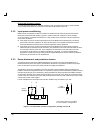
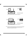
Baldor drives are designed to be powered from standard single and three phase lines (depending on
model) that are electrically symmetrical with respect to ground. Due to the importance of system
grounding for increased reliability, grounding methods are shown in the following sections.