


100
In systems where precise positioning accuracy is required, it is often necessary to position within one
encoder count. The Proportional gain is not normally able to achieve this because a very small
following error will only produce a small demand for the amplifier which may not be enough to overcome
mechanical friction (this is particularly so for current controlled systems). This error can be overcome
by applying some integral gain. The integral gain, KINT, works by accumulating following error over time
to produce a demand/command sufficient to move the motor into the zero following error position. KINT
can therefore also overcome errors caused by gravitational effects, such as vertically moving linear
tables, where with current controlled drives a non-zero demand output is required to achieve zero
following error.
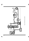
A.1.2 Position loop
The position loop uses a Proportional, Integral, Derivative, Velocity Feedback, Velocity Feed-forward
and Acceleration Feed-forward (PIDVFA) algorithm. Every servo tick, the measured position and
velocity are sampled. The profiler generates a new demand position, speed and acceleration according
to the move type requested and the specified parameters (e.g. the acceleration and deceleration rates).
Both the demanded and measured values are fed into the PIDVFA algorithm, which generates an input
term (demand signal) to either the Speed loop or Current loop (depending upon the configuration).
The PIDVFA algorithm is as follows:
Command =
KP.e + KD.
(
∆e
)
(
∆τ
)
− KV
v
16
+ KF
V
16
+ KI.Σe + KA.A
where:
KP Proportional position loop gain
KD Derivative position loop gain
KV Velocity feedback gain
KF Velocity feed forward gain
KI Integral gain
KA Acceleration feed forward gain
e Following error (quad counts)
τ Servo update period (sample time)
v Actual axis velocity (quad counts/sample time)
V Demand axis velocity (quad counts/sample time)
A Demand axis acceleration (quad counts/sample time
2
)
Tuning the position loop involves selecting values for some or all of the terms KP, KD, KI, KV, KF and
KA to provide the best performance for a particular motor/encoder combination and load inertia. In view
of the diversity of applications, these values all default to zero.