


36
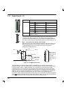
Pin 12 (CREF) controls the sense of all the digital inputs (X13 pins 1 to 9) and should be permanently
wired, dependent on the user requirements, as described below:
Active high: connect +24VDC to pin1 and 0V to pin 12.
The digital inputs will be active when a voltage of +24VDC (±20%) is applied to them and will sink a
maximum o f 2 0 mA.
Active low: connect +24VDC to pin12 and 0V to pin 1.
The digital inputs will be active when grounded and will source a maximum of 20mA.
The +24VDC supply mentioned above is from an externally generated 24VDC supply which should
have a current capability of at least 3A to fulfill all the current requirements of the above loads.
The sense of the inputs can also be controlled individually in Mint using the keyword
INPUTACTIVELEVEL. See also section 2.6 on page 26.
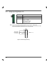
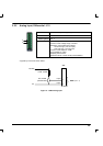
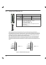
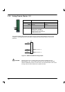
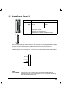
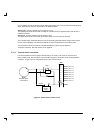
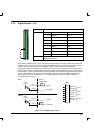
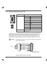
3.3.1.1 Thermal switch connection
It is recommended to wire the motor’s thermal switch, via a relay, to an input on connector X13.
Using suitable code, this provides a way for the Mint program to respond to motor overtemperature
conditions. A typical circuit, using DIN11 as the input, is shown below.
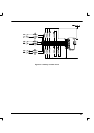
A
B
Motor
thermal switch
connections
CREF
X13
1
12
DIN10 (IN.10)
2
DIN11 (IN.11)
3
DIN12 (IN.12)
4
DIN13 (IN.13)
5
DIN14 (IN.14)
6
DIN15 (IN.15)
7
DIN16 (IN.16)
8
DIN17 (IN.17)
9
Relay
External
24VDC
supply
+24VDC 0V
Figure 16 - Motor thermal switch circuit