Adjustments
Traction Pedal Linkage Adjustment
Traction pedal to reach full stroke prior to contact with
stop.
1. Park machine on a level surface, shut engine off and
lower cutting unit to the floor.
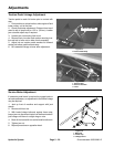
2. Check pedal stop adjustment. Distance from top of
stand to top of stop must be 1.25 in. (32 mm). Loosen
jam nuts and adjust stop if required.
3. Loosen jam nut securing hub to rod.
4. Remove hair pin cotter and washer securing trac-
tion rod hub to lever rod on side of axle assembly.
5. Adjust hub so traction pedal reaches full forward
stroke just before pedal contacts stop.
6. Re–assemble linkage to lever after adjustment.
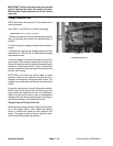
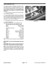
Figure 22
1
1.25 in. (32 mm)
1. Traction Pedal Stop
2
1
3
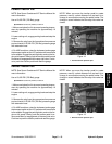
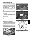
Figure 23
1. Traction Rod
2. Traction Rod Hub
3. Lever
Service Brake Adjustment
If excessive pedal travel is required to engage brake or
as brake pads wear, an adjustment to the brake linkage
may be required.
1. Jack up front of machine and support with jack
stands.
2. Remove left front tire.
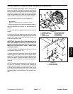
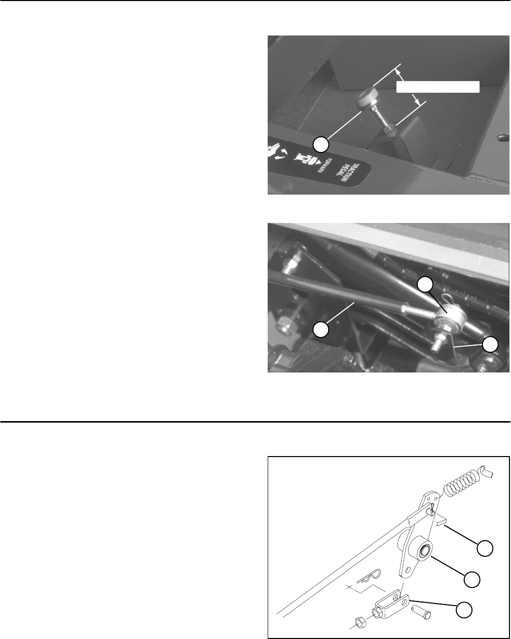
3. With brake linkage bellcrank against frame stop,
loosen jam nut disconnect clevis from bellcrank and ad-
just linkage until there is a slight drag on rotor.
4. Back off clevis one full turn and reinstall to bellcrank.
5. Tighten jam nut.
6. Repeat procedure on opposite wheel.
1
2
3
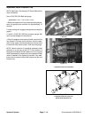
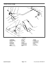
Figure 24
1. Bellcrank
2. Frame stop
3. Linkage Clevis
Hydraulic System
Page 5 – 20
Groundsmaster 3000/3000–D


