


Correcting Cutting Unit Mismatch
If there is mismatch between the blades, the grass will
appear streaked when it is cut. This problem can be cor-
rected by making sure the blades are straight and all
blades are cutting on the same plane.
1. Raise the height–of–cut to the highest position and
lower deck to the floor.
2. Position machine on a level surface on the shop
floor.
3. Shut engine off and engage the parking brake. Un-
lock transport levers.
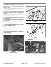
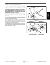
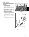
4. Position the tip of an outer blade and adjacent blade
tip as close together as possible at the intersection of the
two cutting chambers. Note the height of the outer blade
tip with respect to the adjacent blade tip.
5. Rotate outer blade 180_ and note the height of the
outer blade tip with respect to the adjacent blade tip. If
the relative height changed by more than 1/8 inch (3
mm) after rotating blade, then outer blade is bent and
should be replaced.
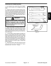
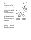
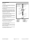
Note: When the blade cutting tips are rotated to their
closest point, the blade in the forward chamber should
be .20 ".13 inch (5 +
3 mm) above the blade of the more
rearward chamber. This is caused by the tilting of each
motor spindle in each individual chamber. The blade
rake is accomplished by titling each spindle rather that
tilting the entire deck. Even with this “apparent mis-
match”, the after cut appearance will not show a mis-
match because each chamber overlaps the adjacent
chamber by 2 inch (51 mm).
6. Repeat steps 3 and 4 until all pairs of adjacent
blades have been checked at both blade tips. Note the
relative difference in blade height at each blade inter-
section after replacing any bent blades. This height dif-
ference should be less than 1/8 inch (3 mm) for all
adjacent blades.
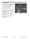
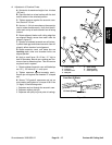
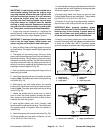
7. Rotate an outer blade until the tip is positioned to-
ward the side of the deck housing. Measure the distance
from the bottom of the blade to the floor. Repeat the
measurement on the opposite side of the deck. If the two
distances differ by more than 1/4 inch (6 mm) proceed to
step 8 and add shims as instructed.
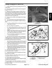
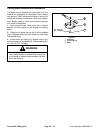
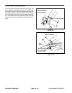
8. Remove capscrews, flatwashers, lockwashers and
nuts from outer spindle in the area where shims must be
added. To raise or lower the blade, add a shim, Part No.
3256–24, between spindle housing and bottom of cut-
ting unit. Continue to check alignment of blades and add
shims until tips of blades are within the required dimen-
sion.
IMPORTANT: Do not use more than three shims at
any one hole location. Use decreasing numbers of
shims in adjacent holes if more than one shim is
added to any one hole location.
Contour 82 Cutting Unit
Page 10 – 14
Groundsmaster 3000/3000–D