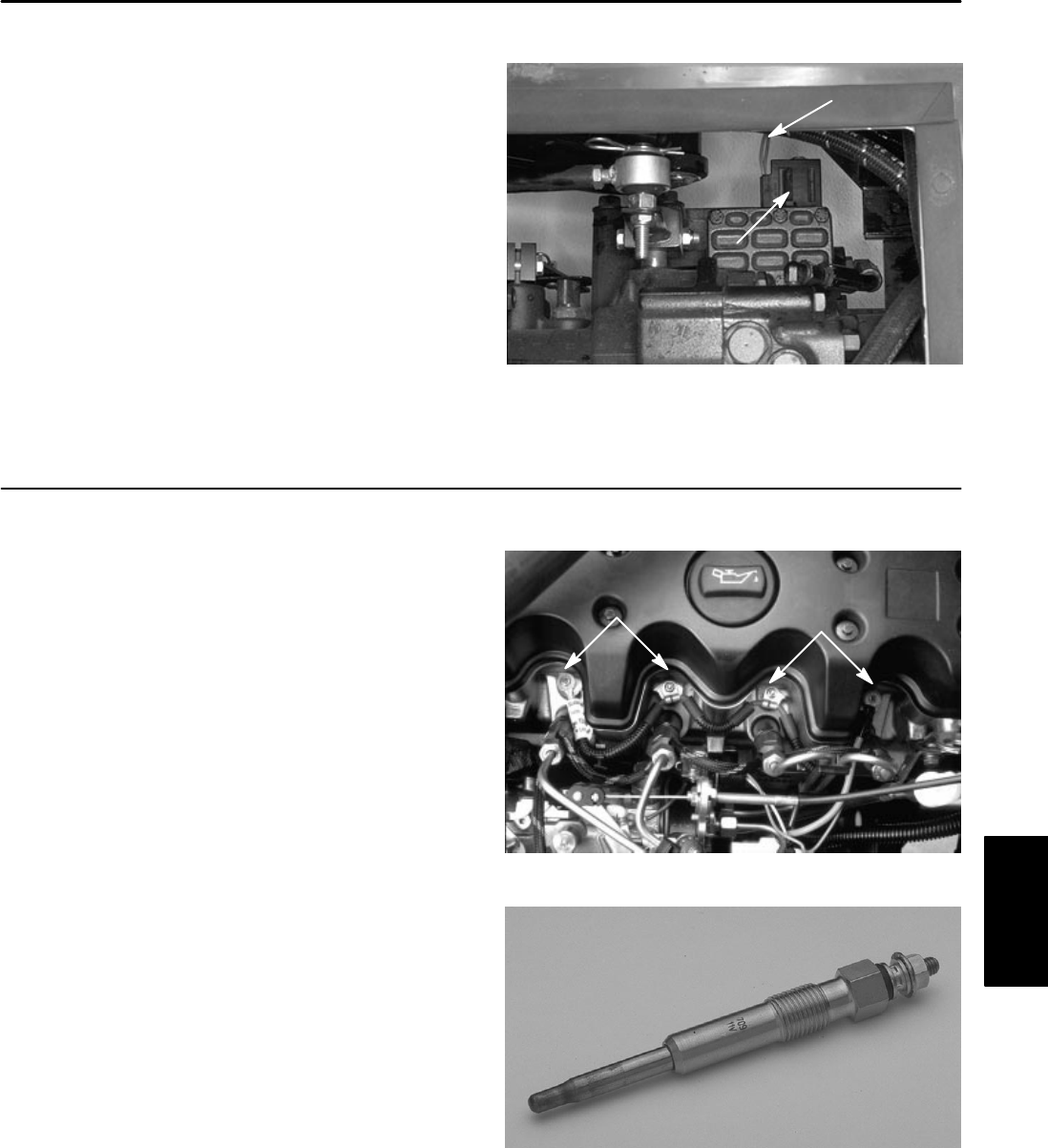
Transport Solenoid (GM 3000–D)
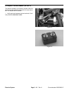
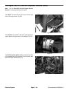
The transport solenoid is located below the seat and on
the front right side of the hydraulic housing.
Note: Prior to taking small resistance readings with a
digital multimeter, short the test leads together. The me-
ter will display a small resistance value (usually 0.5
ohms or less). This resistance is due to the internal re-
sistance of the meter and test leads. Subtract this value
from from the measured value of the component you are
testing.
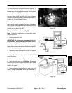
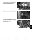
1. Make sure engine is off. Disconnect solenoid elec-
trical connector.
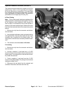
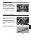
SOLENOID
TO CONNECTOR
2. Apply 12 VDC source directly to the solenoid. Listen
Figure 39
for solenoid to switch on.
3. Measure resistance between the two connector ter-
minals. The resistance should be about 9.0 ohms.
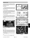
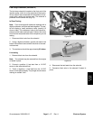
Glow Plugs (GM 3000–D)
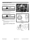
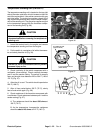
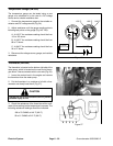
The glow plugs are located on the top of the cylinder
block and on the right side of the engine. They are con-
nected in parallel with black wires to an orange lead wire
(Fig. 40).
Note: Prior to taking small resistance readings with a
digital multimeter, short the test leads together. The me-
ter will display a small resistance value (usually 0.5
ohms or less). This resistance is due to the internal re-
sistance of the meter and test leads. Subtract this value
from from the measured value of the component you are
testing.
1. Disconnect black wire from the glow plug.
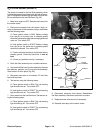
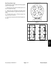
Figure 40
GLOW PLUGS
GLOW PLUGS
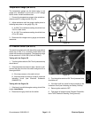
2. Using a digital multimeter, connect one lead to the
post of the terminal and connect the other to the cylinder
block near the plug.
3. The resistance should be about 0.6 to 1.5 ohms.
Figure 41
Electrical
System
Groundsmaster 3000/3000–D
Page 6 – 23 Rev. A
Electrical System


