


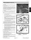

4. Adjustment of Chamber Pivots.
A. Set deck to its maximum height of cut: 4 inches
(102 mm).
B. Place the deck on a level surface with the lock
and lift cables in the unlocked position.
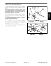
C. Tighten capscrew against the eccentric cam,
then, back off 1/2 turn.
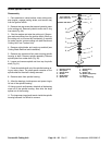
D. Use two 1–1/4 inch wrenches on the eccentric
cam to rotate simultaneously. Verify that identifi-
cation mark on top of each eccentric cam is facing
forward.
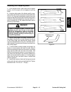
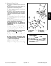
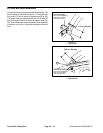
E. Rotate adjacent blades until cutting edge tips
are aligned directly across from each other as
shown in figure 27.
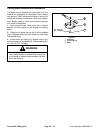
F. Rotation of outboard eccentric cam will primar-
ily effect blade gap and inboard eccentric cam will
primarily effect chamber front alignment.
G. Rotate eccentric cam’s until blade tips are
touching each other and chamber fronts are
aligned parallel.
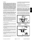
H. Apply a small force (10–15 lbs / 5–7 Kg) to
back of chambers. Be sure non–rotating rear cas-
tors are free to slide along floor. This will remove
any back–lash in system.
I. Rotate outboard eccentric cam until blade tips
are .25 .03 inches (6 +
1 mm) apart.
J. Tighten capscrew against eccentric cam’s.
Secure jam nut against the threaded “C” shaped
wall.
K. Secure 7/16 grade 8 capscrews and nut on
pivot casting and tighten to a torque of 80 ft–lbs
(11 Kgm). in the following order:
1. Capscrew and nut through the eccentric cam.
2. Capscrew without pilot pin.
3. Capscrew with pilot pin (pivot point of casting).
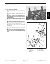
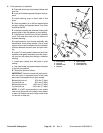
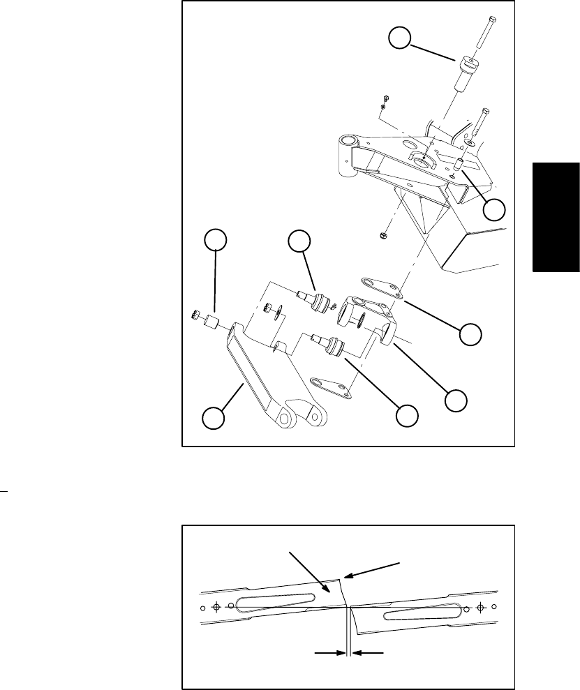
1
2
3
4
4
5
6
7
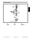
Figure 26
1. Pivot casting 5. Span casting
2. Pivot pin 6. Tapered sleeve
3. Eccentric cam 7. Pivot spacer (2)
4. Ball joint
1/4 inch (6 mm)
Sail
Front Part Of Blade
Figure 27
Contour 82
Cutting Unit
Groundsmaster 3000/3000–D
Page 10 – 17
Contour 82 Cutting Unit