


Groundsmaster 3000/3000–D
Page 5 – 17
Hydraulic System
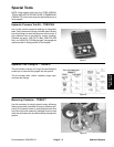
Auxiliary Hydraulic Pump Efficiency Test (Model 30726 Hydraulic Kit)
A worn or damaged pump will by–pass oil and make the
pump less efficient. Eventually, enough by–passing will
occur to cause the cutting units to to stall in heavy cutting
conditions. Continued operation with a worn, inefficient
pump can generate a lot of heat and cause damage to
seals and other components in the hydraulic system.
Use a tester with pressure and flow capabilities.
Specification:
Minimum 12 GPM (45 liter/min.) at 2,500 PSI (173 Bar)
1. Make sure hydraulic oil is at normal operating temper-
ature by operating the machine for approximately 10
minutes.
2. Lower cutting unit, engage parking brake and stop the
engine.
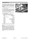
3. Disconnect the large pressure hose from the coupler
at the pump. Disconnect the large return hose from the
coupler at the return filter. Install the tester between the
pump outlet and filter inlet.
IMPORTANT: Make sure the oil flow indicator on the
flow meter shows that the oil will flow from the
pump, through the tester and into the return filter.
Make sure the flow control valve is open before
starting the engine.
4. Start the engine and move the throttle control all the
way forward. Engage the PTO.
5. Slowly close the flow control valve until the gauge
reads 2,500 PSI (173 Bar). Read the flow meter. Disen-
gage the PTO, stop the engine and open the flow control
valve on the tester. If flow is less than 12 GPM (45 liter/
min.) the pump is inefficient and should be repaired or
replaced.
NOTE: The pump has an integral relief valve that is set
at 3,625 PSI (250 Bar). This relief valve protects the
pump from shock stress. If you cannot reach 2,500 PSI
(173 Bar) when closing the flow control valve on the
tester, this relief valve may be stuck open. This could be
caused by debris or contamination in the hydraulic sys-
tem.
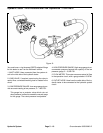
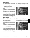
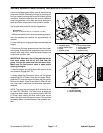
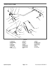
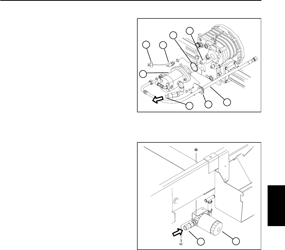
Figure 20
1. 45 degree fitting
2. Quick coupler nipple
3. Pump
4. Splined coupler
5. Flush faced coupler
6. Pump supply hose
7. Hose bracket
8. Square O–ring
1
3
2
4
5
6
7
8
Flow
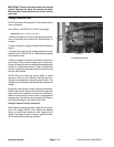
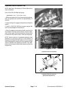
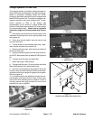
Figure 21
1. Oil filter assembly
2. Flush faced fitting
1
2
Flow
Hydraulic System
and Transaxle