


Governor Adjustment
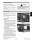
1. With engine shut off, move throttle control to FAST
position and open hood. Check between the throttle arm
and the stop on the carburetor base to make sure there
is 1/32” (0.8 mm). If gap is not correct, adjust throttle rod
by turning ball joint ends until gap is 1/32” (0.8 mm). If
gap is correct, proceed to step 2.
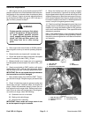
Engine must be running so final adjust-
ment of the governor can be performed.
guard against possible personal
hands, feet, face and other parts of the
body away from fan or other moving
parts.
WARNING
To
injury, engage parking brake and keep
2. Start engine and move throttle to SLOW position.
Allow engine to warm up to normal operating tempera-
ture.
3. Rotate throttle arm closed until it contacts stop.
4. Check idle speed and adjust carburetor idle speed
screw if necessary to attain 1350 +
50 rpm.
5. Release throttle arm, loosen jam nut on governor
low idle speed screw and adjust it to attain 1500 + 100
rpm.
6. Slowly move throttle to FAST position until engine
speed reaches 3150 +
100 rpm. Shut off engine. Adjust
high idle stop screw until it contacts speed control lever.
IMPORTANT: Do not over speed the engine because
the transmission could be damaged.
7. Move throttle rapidly from SLOW to FAST. The en-
gine should not surge. if engine surges, proceed to step
8.
8. Check V–belts from engine to governor pulley and
assure they are tight. If belts are loose, the engine will
surge. If belts are tensioned properly, loosen jam nut
that retains the anti–surge screw. Rotate screw clock-
wise 1/8 turn at a time until surging stops. Should gover-
nor continue to surge, check the following:
A. Carburetor too rich or too lean.
B. Binding in throttle linkage.
C. Governor worn internally.
IMPORTANT: Never rotate anti–surge screw in too
far so that speed of engine increases.
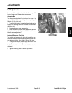
9. Bump the throttle lever with your hand so engine
speeds up momentarily. If governor is working properly,
engine speed should return to normal within one or two
surges of the governor. More than two surges of the gov-
ernor usually indicates than the anti–surge screw must
be turned in slightly more than it is. When adjustment is
correct, lock jam nut against governor body.
10. Check low and high idle speed to be sure there is no
change from the initial setting. If high idle speed has in-
creased, anti–surge has been turned into the governor
too far and it must be backed out. Then repeat the entire
adjustment procedure.
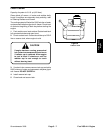
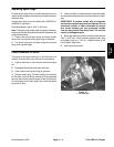
Note: If the throttle control on the instrument panel will
not stay in the FAST position during operation, remove
the panel cover and tighten the nut at base of throttle le-
ver assembly.
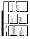
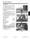
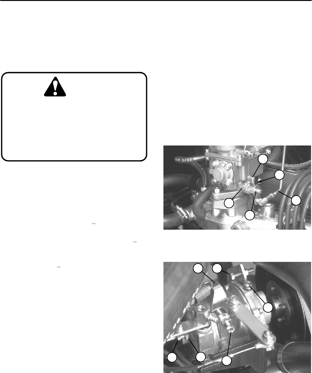
1
2
3
4
5
Figure 2
1. 1/32” (0.8 mm)
4. Stop
2. Throttle rod
5. Throttle arm
3. Carburetor idle speed screw
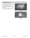
12
3
4
5
6
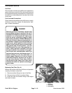
Figure 3
1. High idle stop screw
4. Anti–surge screw
2. Speed control lever
5. Low idle stop screw
3. Jam nut
Ford VSG–411 Engine
Page 3 – 4
Groundsmaster 3000