2
Castor Wheel and Bearing Service
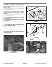
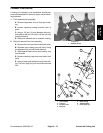
1. Lock transport levers, raise cutting unit to highest
position, shut the engine off and engage the parking
brake.
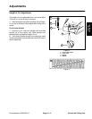
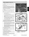
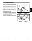
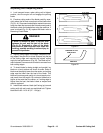
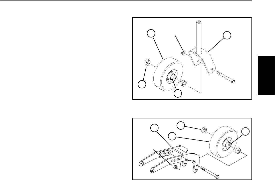
2. Remove locknut from capscrew holding castor
wheel assembly between front castor fork (Fig. 18) or
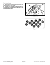
rear castor pivot arm (Fig. 19) Grasp castor wheel and
slide capscrew out of fork or pivot arm.
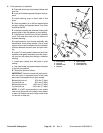
2. Remove bearing from wheel hub and allow bearing
spacer to fall out. Remove bearing from opposite side of
wheel hub.
3. Check the bearings, spacer and inside of wheel hub
for wear. Replace defective parts.
1
3
4
60 – 80 ft–lb
(8 – 11 Kgm)
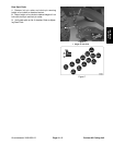
4. To assemble the castor wheel, push bearing into
wheel hub. Slide bearing spacer into wheel hub. Push
Figure 18
1. Castor wheel 3. Bearing (2)
other bearing into open end of wheel hub to captivate the
2. Front Caster Fork 4. Bearing spacer
bearing spacer inside the wheel hub.
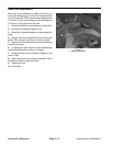
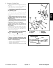
5. Install castor wheel assembly between castor fork
and secure in place with capscrew and locknut. Torque
to 60 – 80 ft–lb (8 – 11 Kgm).
1
3
2
60 – 80 ft–lb
(8 – 11 Kgm)
Figure 19
1. Castor wheel 3. Bearing (2)
2. Rear Caster Pivot Arm 4. Bearing Spacer
Contour 82
Cutting Unit
Groundsmaster 3000/3000–D
Page 10 – 11
Contour 82 Cutting Unit
4


