


SECTION 2 - OPERATION
2-15
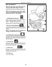
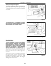
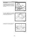
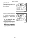
Engine Oil Pressure Gauge
The engine oil pressure gauge, 1, is a
mechanical gauge that has a capillary tube to the
engine to provide oil pressure for the gauge. The
gauge has a 0 to 500 kPa (0 to 75 PSI) display on
its face. The gauge is tied into the Electronic
Instrument Control System to warn the operator
that an unusual engine oil pressure reading is
present during operation. For further information
about the electronic dash module and how it
relates to oil pressure, see “Electronic
Instrument Control System” later in this section.
The gauge also has red (warning) and green
(normal operation) segments on the face of the
gauge to indicate the operating range. The red
(warning) segment, 2, stretches from 0 to 100
kPa (0 to 15 PSI) and indicates the engine is
running at a lower than normal oil pressure. The
green (normal operation) segment, 3, stretches
from 100 to 500 kPa (15 to 75 PSI) and indicates
the engine is running within normal oil pressure
parameters.
Figure 2-22
1
3
2
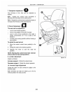
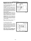
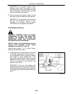
Engine Coolant Temperature Gauge
The engine coolant temperature gauge, 1, is a
mechanical gauge that has a capillary tube to the
engine to provide a coolant temperature reading
for the gauge. The gauge is tied into the
Electronic Instrument Control System to warn
the operator that an unusual engine coolant
temperature reading is present during operation.
For further information about the electronic dash
module and how it relates to engine coolant
temperature, see the “Electronic Instrument
Control System” portion of this section. The
gauge is numberless with two indicator bands on
it to display engine coolant temperature. The
green zone, 2, (normal operating temperature)
ranges from 54°C to 109°C (130°Fto228°F).
The red band, 3, (warning operating
temperature) ranges from 109°C to 121°C
(228°F TO 250°F).
NOTE: On 2360 and 2425 tractors equipped
with electronic engines, the engine coolant
temperature gauge is not tied into the
module. The system has its own temperature
sending unit. See “Electronic Instrument
Control System” portion if this manual for
more information.
Figure 2-23
1
2
3