


SECTION 2 - OPERATION
2-128
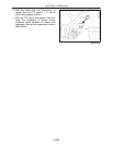
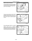
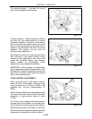
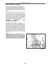
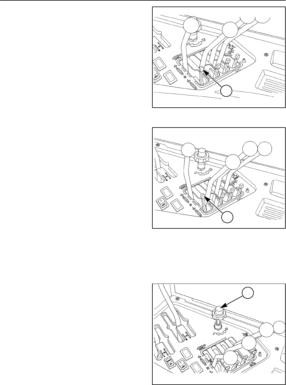
The second position, 1, prevents the control
lever from entering the float position.
Figure 2-170
1
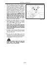
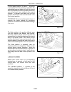
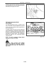
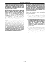
The final position, 1, has twofunctions. It will lock
the lever into the neutral position to prevent
accidental actuation of the lever. If the lockout
lever is moved to this position while the control
lever is in the retract position, the control lever is
limited to travel between the float and retract
positions. This position can be used for
continuous flow applications.
By limiting the travel of the remote control lever
from returning to the neutral position during
continuous flow applications, the lockout will
protect the hydraulic system from pressure
spikes created by hydraulically driven
implements during implement shutdown.
IMPORTANT: When shutting off hydraulically
driven implements, place the remote lever in the
float position to allow the implement to coast to a
stop. Shut the tractor off and place the remote
lever in the neutral position.
Figure 2-171
1
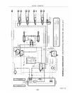
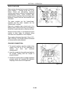
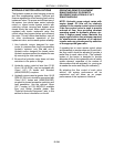
FLOW CONTROL ADJUSTMENT
Each valve spool has a flow control valve to
meter oil flow to that coupler. Flow can range
from a minimum of 11.4 L/min (3 GPM) to full
available flow 114L/min (approximately 30
GPM).
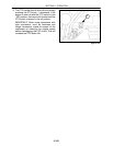
Buhler Versatile 4WD tractors are equipped with
four rotary knob style flow controls as standard
equipment. (1 (grey section) shown in figure
2--195)
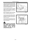
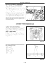
The knob can be rotated counterclockwise to
increase flow and clockwise to decrease flow.
This k nob will control only the grey valve section.
By pushing the button in the center of the knob,
the c ontrol knob can be pulled upward or pushed
downward to change the flow control setting.
Figure 2-172
1