


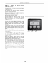

SECTION 2 - OPERATION
2-112
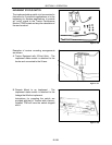
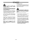
DRAWBAR ASSEMBLY
The drawbar height is fixed and must not be
altered. It is designed to produce maximum
traction for the wheelbase, tire size, weight
distribution and ballast of the tractor. The
drawbar length is nonadjustable andthe hitch pin
distance is 508 mm (20″) fromthe end of the PTO
shaft if the tractor is equipped with the optional
PTO.
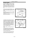
The bolt-on clevis on the manual hitch pin, 1, can
be removed and bolted to the bottom of the
drawbar to accommodate implement and PTO
hookup.
IMPORTANT: A clip pin must be installed
through the drawbar pin to hold it when the clevis
is flipped over for PTO use.
IMPORTANT: This arrangement is not approved
with the Automatic Hitch Pin.
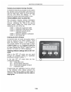
Figure 2-146
19992760
1
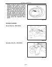
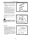
Figure 2-147
1
2
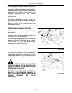
The drawbar is free-- swinging and should be
positioned for the best performance and the
least side draft. There are five drawbar
positions on a unit without a 3--point hitch
option. To swing the drawbar, pull the hairpin
clips, 1, from the wear blocks, 2. Remove the
wear blocks, swing the drawbar to the desired
position, and reinstall the wear blocks. On
tractors without 3--point hitch, onesingle pin is
used on any position except the center
position, where two are used.
NOTE: Drawbar with Manual Hitch Pin
shown.
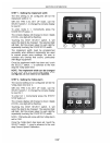
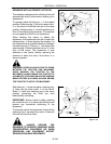
On tractors that have a 3-point hitch installed,
both wear block pins can be installed when
the drawbar is swung to the right or left
position. Three-point hitch equipped tractors
have three drawbar positions.
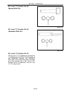
Choose a position that is right for the job and
insert the pin and wear block(s) in that
position to keep the drawbar from moving.