


SECTION 2 - OPERATION
2-119
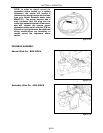
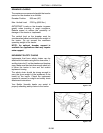
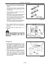
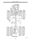
4. Be sure that the PTO drive shaft halves have
adequate overlap and will not separate when
turning.
Pull drive halves apart until fully extended,
just before they come completely apart. This
is dimension A.
From dimension A, subtract 152.4mm (6″),
establishing dimension B.
IMPORTANT: Never operate equipment with
the driveline extended past dimension B.
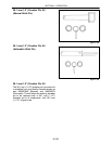
Push drive halves together as far as possible.
This i s dimension C. Add 25.4mm (1″)to
dimension C to establish dimension D.
IMPORTANT: Never operate equipment with
the driveline collapsed past dimension D.
Figure 2-156
DIM “D” EQUALS
DIM “C” + 25.4MM (1 in.)
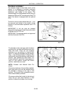
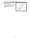
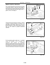
5. Be sure that all shields are in place and in
good condition. They must fully shield the
driveline.
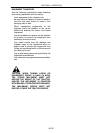
6. Ensure that the PTO master shield, 1, is in
position.
DANGER: NEVER REMOVE OR ALTER THE
PTO MASTER SHIELD AT ANY TIME TO
ASSIST IN ATTACHING ANY TYPE OF
IMPLEMENT.
Figure 2-157
1
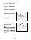
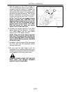
PTO Operation
1. Stop the engine and park the tractor. Connect
the drawbar to the implement hitch. Turning
the engine off releases the PTO brake,
allowing the stub shaft to be hand turned for
spline alignment. Be sure the drive shafts are
straight for easier connection.
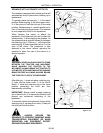
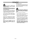
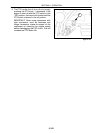
2. Attach the implement drive shaft to the tractor
output shaft. Check for adequate telescope
action and for clearance to the surrounding
frame. The drawbar clevis, 1, can be flipped
over to provide additional clearance for the
PTO drive shaft.
Figure 2-158
1