


SECTION 1 - GENERAL INFORMATION
1-32
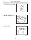
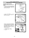
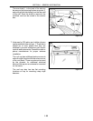
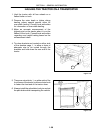
The bus bar pins are identified as follows:
Pin 1 is a switched 12 -volt power source
that is live when the ignition is in the “RUN”
position (10-amp circuit protection).
Pin 2 is a switched 12 -volt power source
that is live when the rotary light switch is in
the roadway or field use positions (3-amp
circuit protection).
Pin 3 is a ground pin.
Pin 4 is a secondary source for external
signals to access the external alarm
control of the Electronic Instrument
Control System.
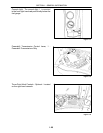
For more information on how to hook up the
external alarm control, see the “Electronic
Instrument Control System” section of this
manual.
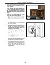
NOTE: The cowling that secures the bus
bar and fuel gauge has circular scribe
marks that can be cut out for installing
additional gauges. The scribe marks are
sized to standard size gauges.
Figure 1-48
2
1
34
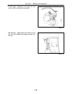
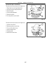
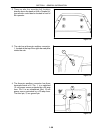
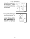
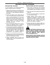
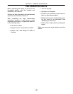
6. To route umbilical cords to a monitor box,
remove the cover plate, 1, on the underside of
the right rear corner of the cab and route the
cord up into the c ab.
Figure 1-49
1