


SECTION 2 - OPERATION
2-144
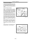
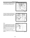
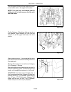
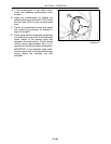
Turn the upper lift link end over end and mount it
to the bottom hole in the upper link bracket.
NOTE: Turn end over end means that the
hitch point of the link becomes the link point
and vice versa.
Figure 2-204
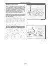
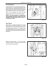
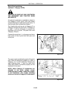
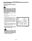
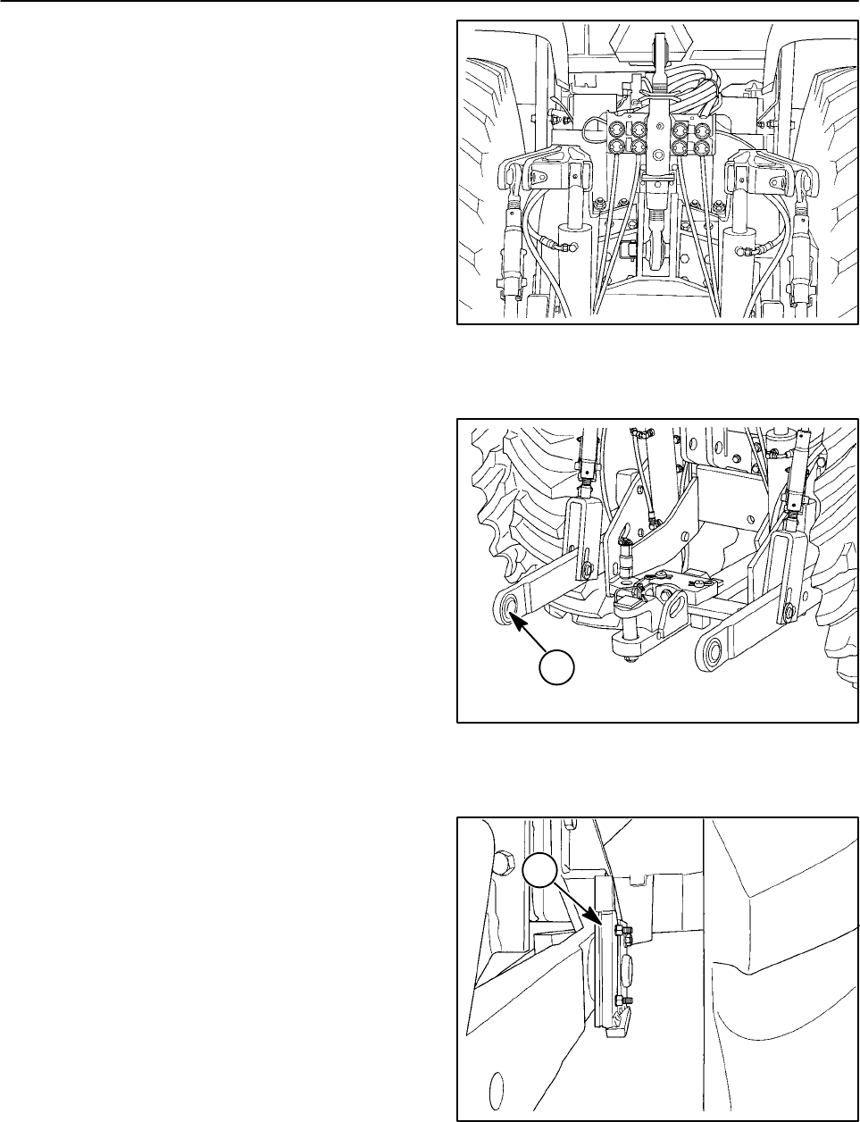
Put the Category III bushings that are stored on
the drawbar cage storage pin into the ball
swivels, 1, at the upper and lower link hitch
points.
Figure 2-205
1
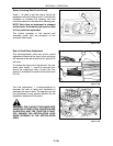
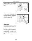
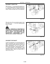
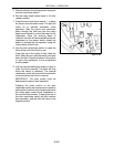
Add or remove shims, 1, to ensure that the lower
links do not contact the tires when they arefree of
the implement.
Reverse these steps to convert from a Category
III to Category IV Narrow.
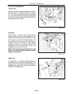
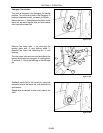
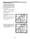
Be sure that the correct diameter pins are used in
the hitch attaching points. Undersized pins may
break and damage the implement or ball ends.
IMPORTANT: Use the correct diameter pins in
the 3-point attaching links. Category III upper link
pin size: 32 mm (1 -1/4″) diameter. Lower link pin
size: 37 mm (1-7/16″) diameter. Category IVN
upper link pin size: 45 mm (1-3/4 ″)diameter.
Lower link pin size: 50 mm (2″)diameter.
Figure 2-206
1