


3-14 PULSE MODULATION
TESTS: RISE TIME,
FALL TIME, OVER-
SHOOT, AND LEVEL
Pulse modulation tests verify correct operation as
well as rise time, fall time, overshoot, and level. The
pulse leveling accuracy test compares the pulsed RF
output level to verify the performance of the level
detector(s), detector amplifiers, and ALC sample/
hold circuits.
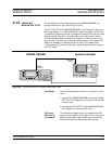
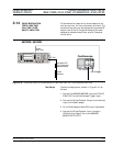
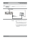
Test Setup
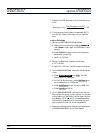
Connect the equipment, shown in Figure 3-10, as
follows:
1. Connect the 682XXB/683XXB rear panel PULSE
SYNC OUT to the Oscilloscope Trigger Input.
2. Connect the Pulse Detector Output to the Vertical
Input of the Oscilloscope.
3. On the Oscilloscope, select 50W input impedance.
4. Connect the Pulse Detector Input through a
150 MHz High Pass Filter to the 682XXB/
683XXB RF OUTPUT.
682XXB/683XXB MM 3-39
PERFORMANCE PULSE MODULATION TESTS:
VERIFICATION RISE TIME, FALL TIME, OVERSHOOT, AND LEVEL
RF Out
Pulse
Detector
150 MHz HPF
(For Overshoot
Measurement)
CH. 4 Trigger
682XXB / 683XXB
Pulse
Sync Out
CH. 2 Input
Oscilloscope
Figure 3-10. Equipment Setup for Pulse Modulation Tests: Rise Time, Fall Time, Overshoot, and Level