


4-12 AM CALIBRATION This procedure provides the steps necessary to perform AM calibra
-
tion. This consists of calibrating the AM Calibration DAC, the AM Me
-
ter circuit, and the AM Function Generator. The AM Calibration DAC
is calibrated for input sensitivities of 100%/V (linear mode) and
25 dB/V (logarithmic mode) for frequencies £2 GHz and >2 GHz.
Equipment
Setup
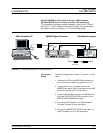
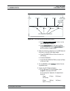
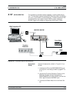
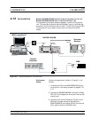
Connect the equipment, shown in Figure 4-10, as
follows:
1. Interface the PC to the 682XXB/683XXB by per
-
forming the initial setup procedure, pages 4-7 to
4-12.
2. Connect the Function Generator Output to the
BNC tee. Connect one leg of the tee to the
682XXB/683XXB front panel AM IN. Connect the
other leg of the tee to the DMM input.
3. Calibrate the Power Meter with the Power Sen
-
sor.
682XXB/683XXB MM 4-33
AM
CALIBRATION CALIBRATION
RF
OUT
Power Meter
Power
Sensor
Serial
I/O
682XXB / 683XXB
COM1
or
COM2
IBM-Compatible PC
Function
Generator
OUTPUT
AM
IN
BNC
Tee
INPUT
DMM
Figure 4-10. Equipment Setup for AM Calibration