


4-8 SWITCHED FILTER
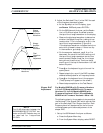
SHAPER CALIBRATION
This procedure provides the steps necessary to adjust the Switched
Filter Shaper Amplifier gain to produce a more constant level ampli
-
fier gain with power level changes.
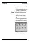
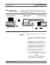
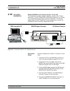
Equipment
Setup
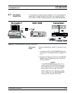
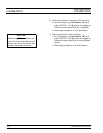
Connect the equipment, shown in Figure 4-3, as fol-
lows:
1. Interface the PC to the 682XXB/683XXB by per-
forming the initial setup procedure, pages 4-7 to
4-12.
2. Using the Auxiliary I/O cable, connect the
682XXB/683XXB rear panel AUX I/O connector to
the 562 Network Analyzer AUX I/O connector.
3. Using the GPIB cable, connect the 562 Network
Analyzer DEDICATED GPIB connector to the
682XXB/683XXB IEEE-488 GPIB connector.
4. Connect the RF Detector to the 562 Network
Analyzer Channel A Input connector.
5. Connect the 682XXB/683XXB RF OUTPUT con
-
nector to the RF Detector via a 10 dB Attenuator.
NOTE
Before beginning this calibration proce
-
dure, always let the 682XXB/683XXB
warm up for a minimum of one hour.
682XXB/683XXB MM 4-17
Serial
I/O
682XXB / 683XXB
COM1
or
COM2
IBM-Compatible PC
562 Network Analyzer
10 dB
Attenuator
GPIB AUX
I/O
RF Detector
Dedicated
GPIB
RF
Output
A
AUX
I/O
Figure 4-3. Equipment Setup for Switched Filter Shaper Calibration
SWITCHED FILTER
CALIBRATION SHAPER CALIBRATION