


5-22 682XXB/683XXB MM
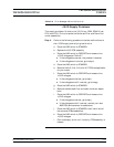
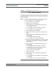
±15VA Supply Problems
This supply provides ±15 volts to the Function Generator, PIN Control,
ALC, FM, and Analog Instruction circuits.
Step 5. Perform the following procedure to isolate malfunctions to
the ±15VA supply and outlying load circuits.
a. Place the LINE switch to STANDBY.
b. Replace the A15 PCB assembly.
c. Place the LINE switch to OPERATE and measure the
±15VA voltages per Table 5-7.
If the voltages are correct, the problem is cleared.
If the voltages are incorrect, go to step d.
d. Place the LINE switch to STANDBY.
e. Remove the A8, A9, A10, A11, and A12 PCBs.
f. Place the LINE switch to OPERATE and measure the
±15VA voltages.
If the voltages are correct, go to step g.
If the voltages are still incorrect, contact your local
ANRITSU service center for assistance.
g. Place the LINE switch to STANDBY, then install one of
the removed PCBs.
h. Place the LINE switch to OPERATE and measure the
±15VA voltages.
i. Continue steps g and h until the faulty PCB is located.
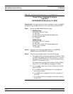
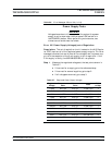
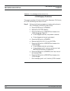
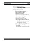
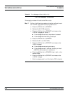
Table 5-6. Error Messages 105 and 106 (4 of 10)
TROUBLESHOOTING
TROUBLESHOOTING TABLES