682XXB/683XXB MM 5-31
Step 6. Using the spectrum analyzer, verify the presence of the
+3 dBm ±5 dB, 10 MHz signal at the end of the cable.
If present, replace the A4 PCB.
If not present, go to step 7.
Step 7. Disconnect cable W105 at A3J4.
Step 8. Using the spectrum analyzer, verify the presence of the
+3 dBm ±5 dB, 10 MHz signal at A3J4.
If present, replace the cable W105.
If not present, replace the A3 PCB.
Step 9. Reconnect cable W121 to A5J5 and disconnect cable W107 at
A5J1.
Step 10. Set up the 682XXB/683XXB to generate the CW frequencies
listed in Table 5-10.
Step 11. Using a spectrum analyzer, measure the frequency and am-
plitude of the signal at A5J1 for each of the CW frequencies
generated. In each case, the signal amplitude should be
+3 dBm ±3 dB with sidebands at <–65 dBc.
If the signals are correct in both frequency and amplitude,
go to step 12.
If the signals are incorrect, replace the A5 PCB.
Step 12. Reconnect cable W107 to A5J1 and run self-test again.
If error 111 is not displayed, the problem is cleared.
If error 111 is still displayed, contact your local ANRITSU
service center for assistance.
Table 5-9. Error Message 111 (2 of 2)
TROUBLESHOOTING
TROUBLESHOOTING TABLES
682XXB/683XXB
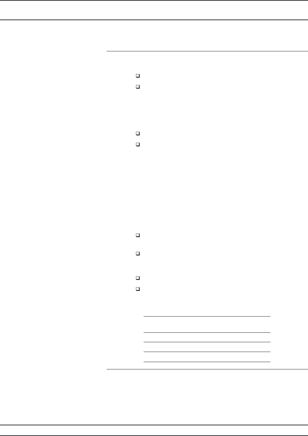
CW Frequency
Measured Frequency
at A5J1
10.102 GHz 22 MHz
10.110 GHz 30 MHz
10.120 GHz 40 MHz
Table 5-10. Fine Loop Frequencies


