5-52 682XXB/683XXB MM
TROUBLESHOOTING
TROUBLESHOOTING TABLES
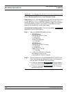
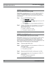
Error 147 Internal FM circuitry failed
Description: Indicates a failure of the internal frequency modulation
function. The 682XXB/683XXB may or may not provide frequency
modulation of the RF output signal using modulating signals from an
external source.
Step 1. Set up the 682XXB/683XXB as follows:
a.
Press SYSTEM , then Reset .
b.
Press MODULATION , then FM to go to the Internal FM
Status display.
c.
Press On/Off to turn internal frequency modulation on.
Step 2. Using an oscilloscope, verify the presence of a 10 volt peak to
peak sine wave signal with a period of 100 ms at the rear
panel FM OUT connector.
If present, replace the A11 PCB.
If not present, replace the A8 PCB.
Table 5-26. Error Message 147
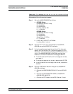
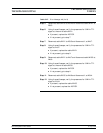
Error 148 Pulse 40 MHz reference circuitry failed.
Description: Indicates a failure of the pulse generator 40 MHz oscilla
-
tor circuitry. The pulse generator may still function; however, the
40 MHz oscillator is not phase locked to the 10 MHz reference time
-
base. The pulse modulation function may or may not operate. Error 106
(Power Supply not Phase-locked) may also be displayed.
Step 1. Disconnect cable W108 at A6J1.
Step 2. Using an oscilloscope, verify the presence of a 10 MHz at the
end of cable W108.
If present, replace the A6 PCB.
If not present, go to step 3.
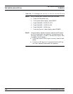
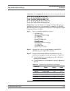
Step 3. Reconnect cable W108 to A6J1 and disconnect it at A5J4.
Step 4. Using the oscilloscope, verify the presence of a 10 MHz TTL
signal at A5J4.
If present, replace the cable W108.
If not present, go to step 5.
Table 5-27. Error Message 148 (1 of 2)


