


3-11 POWER LEVEL
ACCURACY AND
FLATNESS TESTS
The following tests can be used to verify that the 682XXB/683XXB
meets its power level specifications. Power level verification testing is
divided into two parts—power level accuracy tests and power level
flatness tests.
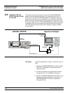
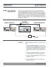
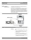
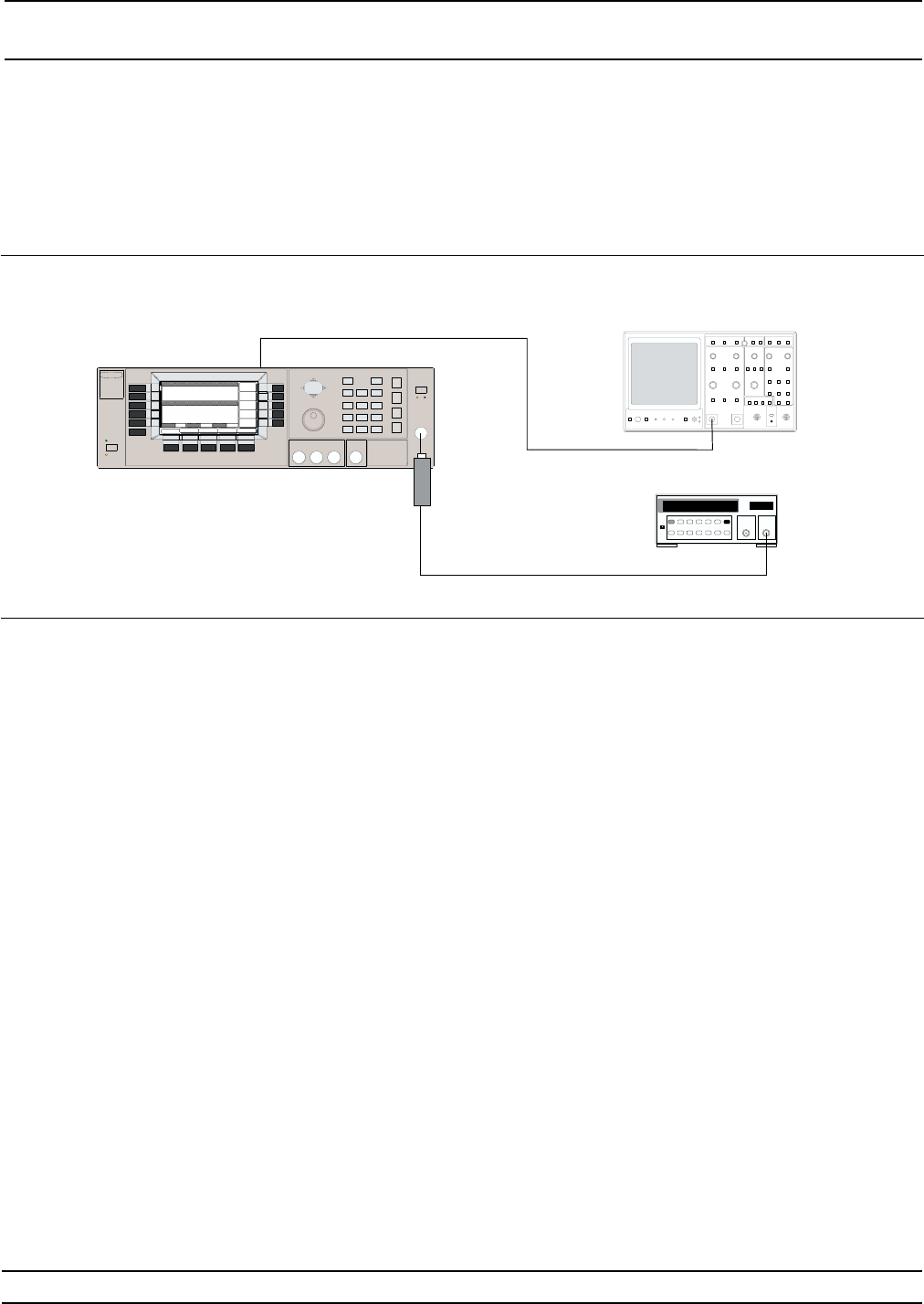
Test Setup
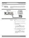
Connect the equipment, shown in Figure 3-6, as fol-
lows:
1. Calibrate the Power Meter with the Power Sen
-
sor.
2. Connect the Power Sensor to the RF OUTPUT of
the 682XXB/683XXB.
NOTE
For £40 GHz models, use the K (male) to
2.4 mm (female) adapter to connect the
Power Sensor to the RF OUTPUT connec
-
tor.
3. Connect the 682XXB/683XXB rear panel HORIZ
OUT to the Oscilloscope CH.1 input (X input).
NOTE
During this test it will be necessary to
adjust the Power Meter’s CAL FACTOR %
setting as applicable for the frequency
being tested.
3-26 682XXB/683XXB MM
RF
OUT
HORIZ
OUT
682XXB / 683XXB OSCILLOSCOPE
Power
Sensor
POWER METER
CH 1 or X Input
Figure 3-6. Equipment Setup for Power Level Accuracy and Flatness Tests
PERFORMANCE POWER LEVEL ACCURACY
VERIFICATION AND FLATNESS TESTS