


4-14 PHASE MODULATION
(FM) CALIBRATION
This procedure provides the steps necessary to perform phase modula
-
tion (FM) calibration for 682XXB/683XXBs with Option 6. This con
-
sists of calibrating the FM Variable Gain Control DAC and the FM
Flatness DAC for input sensitivities in Narrow and Wide FM modes.
Equipment
Setup
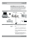
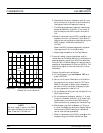
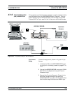
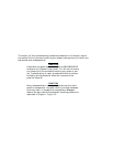
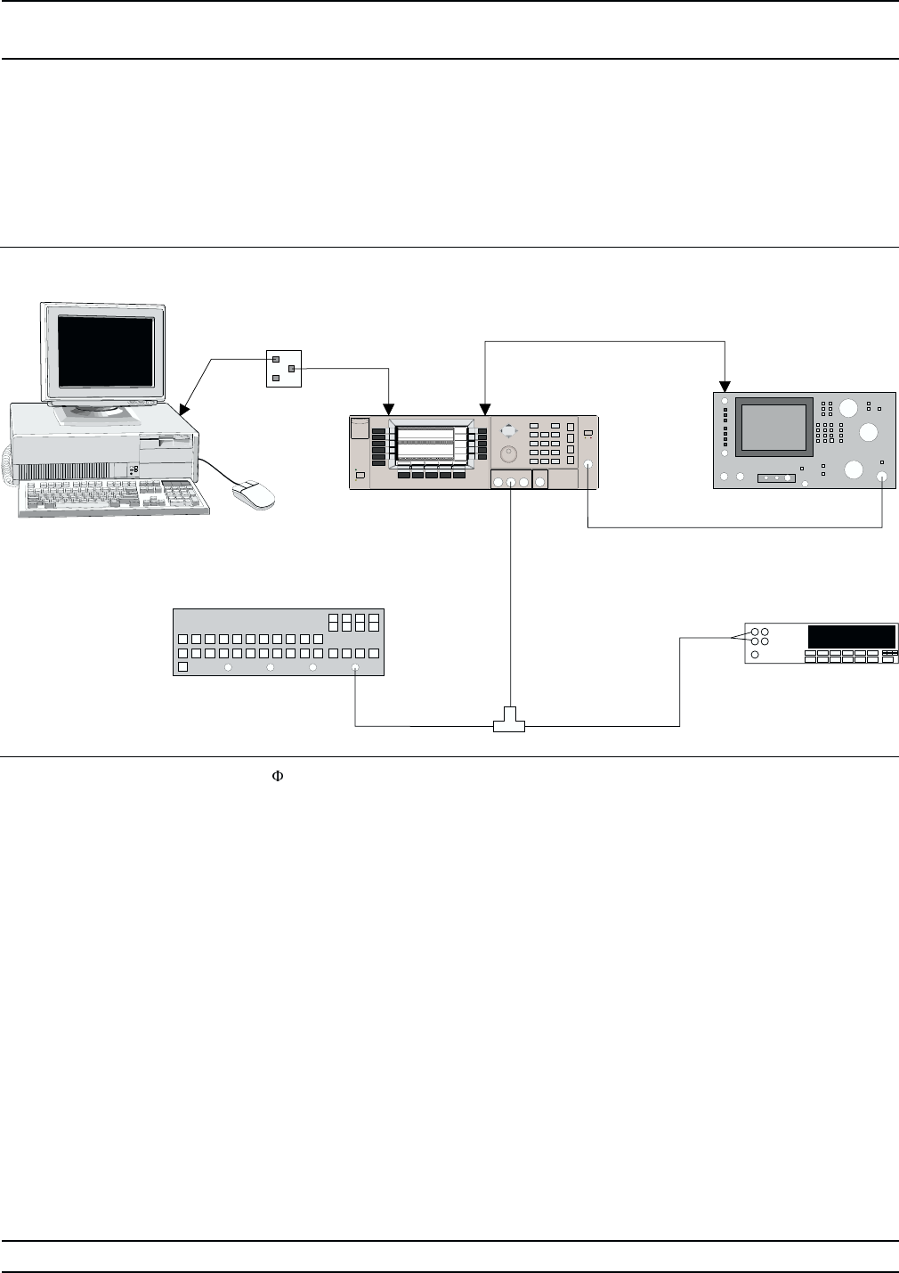
Connect the equipment, shown in Figure 4-15, as
follows:
1. Interface the PC to the 682XXB/683XXB by per
-
forming the initial setup procedure, pages 4-7 to
4-12.
2. Connect the 682XXB/683XXB rear panel 10 MHz
REF OUT to the Spectrum Analyzer External
Reference Input.
3. Connect the Function Generator Output to the
BNC tee. Connect one leg of the tee to the
682XXB/683XXB front panel FM IN (FM IN). Con
-
nect the other leg of the tee to the DMM input.
682XXB/683XXB MM 4-51
PHASE MODULATION
CALIBRATION (FM) CALIBRATION
Serial
I/O
682XXB / 683XXB
COM1
or
COM2
IBM-Compatible PC
Function
Generator
10 MHz
REF OUT
EXT REF
INPUT
RF
IN
Spectrum
Analyzer
OUTPUT
FM IN
(
Φ
M IN)
RF
OUTPUT
BNC
Tee
INPUT
DMM
Figure 4-15.
Equipment Setup for M Calibration